
E-Locker Installation Guide with Eaton E-Locker on Rear 3rd Member on 5th Gen 4Runner
One of my biggest regrets about buying my used SR5 4Runner was the fact that it didn’t have a rear locker.
For the last 6 years of ownership, ATRAC did the job most of the time but as the trails got more technical it became sketchier and sketchier to use when things got tippy. I longed for the days of non-dramatic climbs up uneven terrain.
A locker was always on the mod list but I kept putting it off because I seemed to get by and when I didn’t I just used my winch. However, with plans to take on the Rubicon this year, I knew it was time to pony up and get one installed.
I was originally planning on going with an ARB air locker but after reading about issues with leaks and heavier maintenance requirements I knew an e-locker would be better for me. Eaton recently released an e-locker for the 5th gen so I thought I would give it a try.
My original plan was to have a differential specialist do the install since I assumed it would require a lot of specialized tools and experience.
I’m an avid DIYer but to me, this seemed like a pretty tall job to tackle especially since I had zero experience with gearing and differentials in general. However, after doing a ton of research and watching hours of Youtube videos I decided to throw caution into the wind and give it a go.
Spoiler alert: It’s not as hard as you would think.
Tools and Materials
- (2) Differential Carrier Bearings (Rear) – OEM Part# 9036650130
- (1) Rear Differential Carrier gasket – OEM Part# 4218160140
- (2) Drain plug crush washers – OEM Part# 1215710010
- Carrier Shim Pack for a Dana 44 axle (Call East Coast Gear Supply for this)
- 3 Litres of 75w90 Gear Oil (I use Mobil 1 Synthetic)
- 2” Unthreaded pipe to press the carrier bearings onto the new differential
- 12 Ton Shop Press
- Gear Marking Compound to help confirm backlash is correct
- Dial Indicator to measure gear backlash
- Torque Wrench
- Various Metric sockets and swivel joints
- Rubber mallet
- Heat gun or Propane Torch
- Drill and associated drill bits
- High-temperature RTV
- Wire Loom
E-Locker Installation Guide
Step 1. Preparing Your Vehicle
I won’t go into this in detail but make sure your rear axle is elevated and on jack stands, the wheels are removed, the battery is disconnected and the rear differential fluid is drained. For reference here is a great article on how to drain and fill your rear differential.
Step 2. Unbolt Rear Sway Bar

In order for you to get enough space to remove the third member of the axle from the axle housing you will need to unbolt the rear swaybar from the axle and frame. Unbolt the swaybar from the main axle housing using a 14mm socket and unbolt the swaybar endlinks from the frame using a 10mm wrench.
Step 3. Remove Additional Components From the Axle Housing

In order for us to have enough play to pull the axle shafts partially out, you will need to loosen a few things. Start by removing the emergency brake line bracket from the rear axle’s lower control arm using a 12mm socket. Repeat on the other side.

Next, we will need to remove the retaining tab holding the brake line to the rear hub assembly from both sides of the axle. I used a pair of needle-nose pliers to do this.

Finally, you will want to unbolt the rest of the brake line from the axle using a 12mm socket and also unplug the ABS speed sensors from the rear hub assembly on both sides.
Step 4. Dislodge the Axle Shafts From the Axle Housing

Now it’s time for us to pull out both the axle shafts so we can remove the third member. When doing this please take extra care not to damage the inner and outer axle seals. This seems to be a common mistake for installers and will eventually lead to seal failure.
Unbolt the rear axle shaft from the housing using a 17mm socket, there are four bolts as pictured. Repeat on the other side.
Once both shafts are unbolted, gently pull them out being mindful of the brake lines. I had them out about 2 inches on each side, you just need them out enough to disengage them from the differential.
Step 5. Remove the Third Member From the Axle Housing

We will now need to remove the third member from the axle housing. I neglected to do this but I highly recommend you place match marks on the driveshaft and differential flanges so you can match them up when you bolt everything back together. Remove the four bolts holding the driveshaft onto the differential using a 14mm socket and wrench.
Once the bolts are removed use a rubber mallet to tap the differential off of the third member. You may need to use a bit of force here as rust sometimes fuses these two components together. Make sure you catch the driveshaft before it hits the floor and put it aside.
Next, you will have to use a 14mm socket to remove the nuts holding the third member onto the axle housing. Some of the top nuts may require a swivel joint.

Once all of the nuts are removed gently wiggle the third member out of the axle housing. If the axle shafts are disengaged this should be a relatively easy step since the swaybar should just push out of the way. Be careful when doing this, the third member is relatively heavy and awkward to hold.
Step 6. Disassemble the Third Member
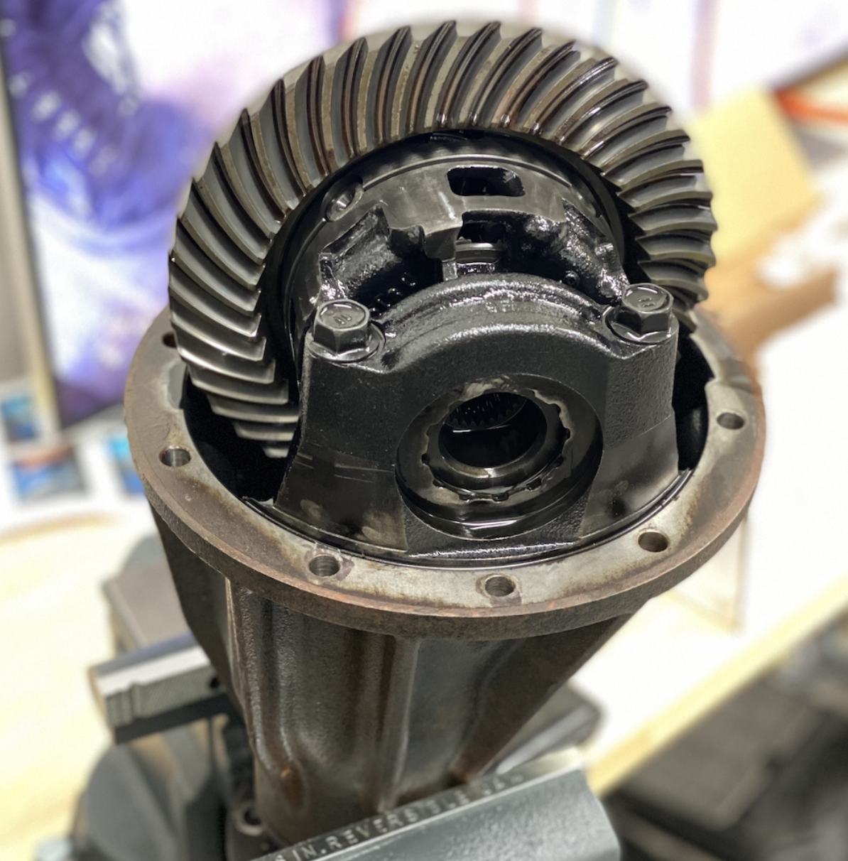
Well, you did it! The differential is finally out, place the third member in a vise and make sure it’s securely clamped down.
Before removing the differential from the housing you will want to put matching marks on the bearing caps. These units are machined together so they must be reassembled in the correct orientation. I used a metal punch to accomplish this.
Remove the four bearing cap bolts with a 17mm socket.

Once the bolts and bearing caps are removed you should be able to remove the differential from the housing. Technically, you are supposed to use a differential spreader to get this thing out but I just carefully used a pry bar and it popped right out. If you choose to use this method be careful of the pinion gear and make sure you are prying on safe surfaces.

Once the differential is out you will want to remove the ring gear off of it by using a 17mm socket to remove all of the gear bolts. These suckers are on tight so I had to use a combination of an impact wrench and heat gun to get them out.
Step 7. Prepare the New Locking Differential

I originally wanted to buy a shop press to help me with this project but there is a steel shortage and I couldn’t get my hands on one. Either way, you will need to press the two new OEM carrier bearings onto your Eaton differential which can be accomplished by using a press and that piece of 2″ pipe listed in the tools you need section. I was lucky enough to have a transmission shop locally who did the job for me in 2 mins and for $20.
Once you have the bearings pressed on you will need to reattach your OEM ring gear onto your Eaton differential reusing the bolts from your original differential. You may need to use some heat on the gear to expand it enough so that it slides right on. Use red loctite on the threads of all the bolts and tighten them in a star shape pattern. The bolts need a 17mm socket and need to be torqued down to 71 ft lb. I also put matchmarks on the bolts so in the future I could tell if there was any loosening.

You will now need to drop the new differential into the third member housing. Before we can do that we will need to figure out how much side preload the new differential needs in the carrier. This takes a bit of guess work and testing so be patient. Reassemble the bearing races and pick a set of shims from your shim pack that allow the differential to sit in the carrier pretty snug.

Once the differential is in you will need to measure the ring gear backlash using a dial indicator. There are many videos out there that explain how to use a dial indicator but I found this one to be the most helpful to reference. You will need to get it to the stock range which is anywhere between 0.00394 to 0.00709 in. To adjust the backlash or distance between the ring and pinion gear you will need to change the thickness of the preload shims on each side of the differential.
- For More Backlash – Use thinner shims on the left side and thicker shims on the right
- For Less Backlash – Use thicker shims on the left and thinner shims on the right

Once you get a good readout you will need to reinstall the bearing caps, but before we can do this we will need to tweak the anti-rotation bracket on the locker. This bracket needs some play in it so the locker can engage and disengage. So we will need to make some adjustments. Bend the bracket out a bit on each side so that it has some room to move with the bearing caps reinstalled.

How much play is needed? Great question, here is a video that I recorded that illustrates how much play I ended up with on my install, and everything seems to be working fine.
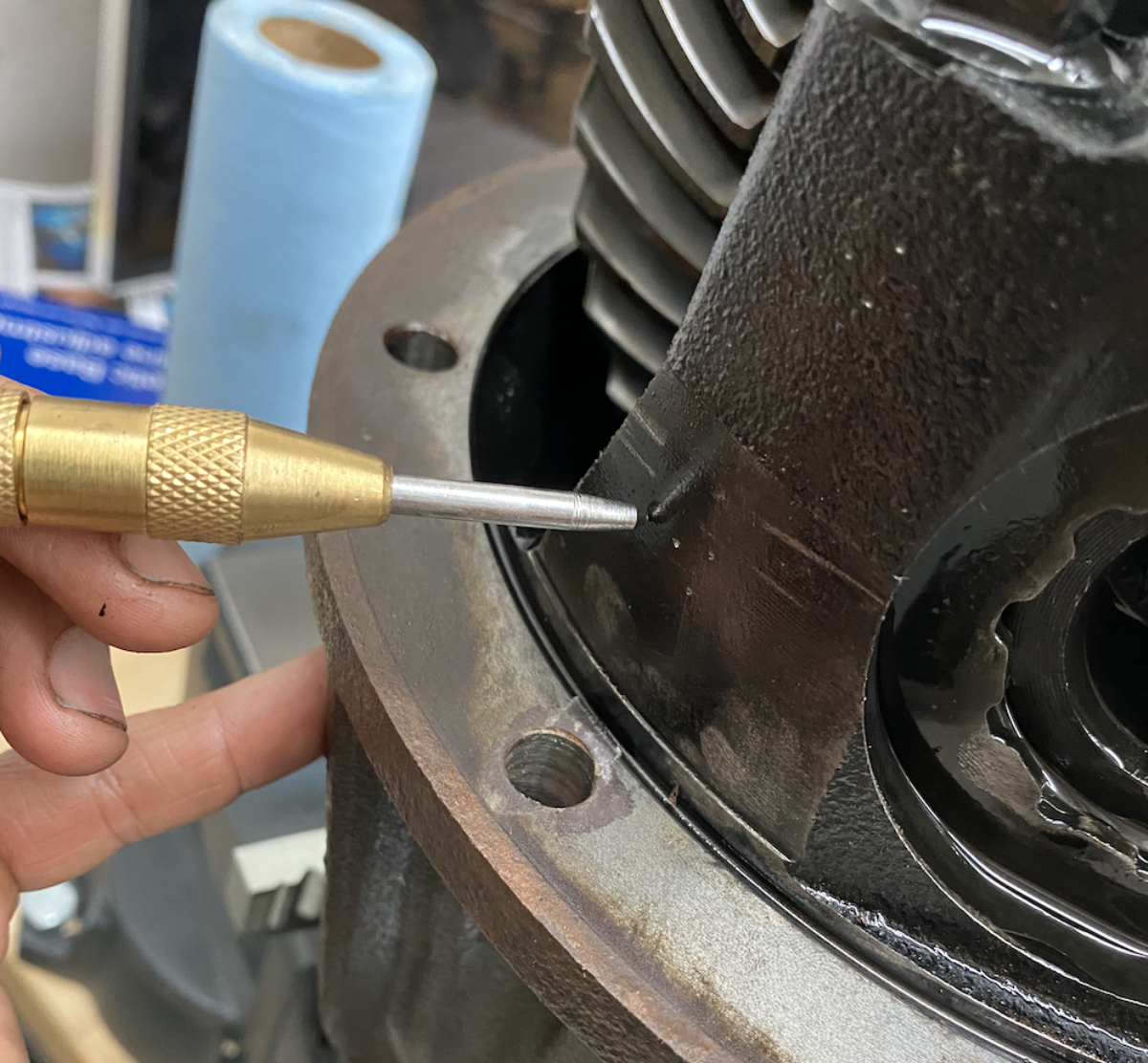
Once you get the bracket all set up you will need to remove the differential and drill a hole in your third member housing so you can pull through the wiring that is required to activate your locker. Make sure you put some protection in your differential housing to ensure metal fragments don’t get inside. I chose to go for a spot on the upper right quadrant of the housing since the wiring pig tail was pretty short.
WARNING: DO NOT cut the included zip tie that holds the wiring to the anti rotation bracket. I made the mistake of doing that and later found out it’s a highly specialized high-temperature zip tie that is not easy to source!
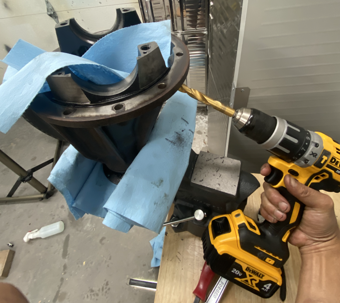

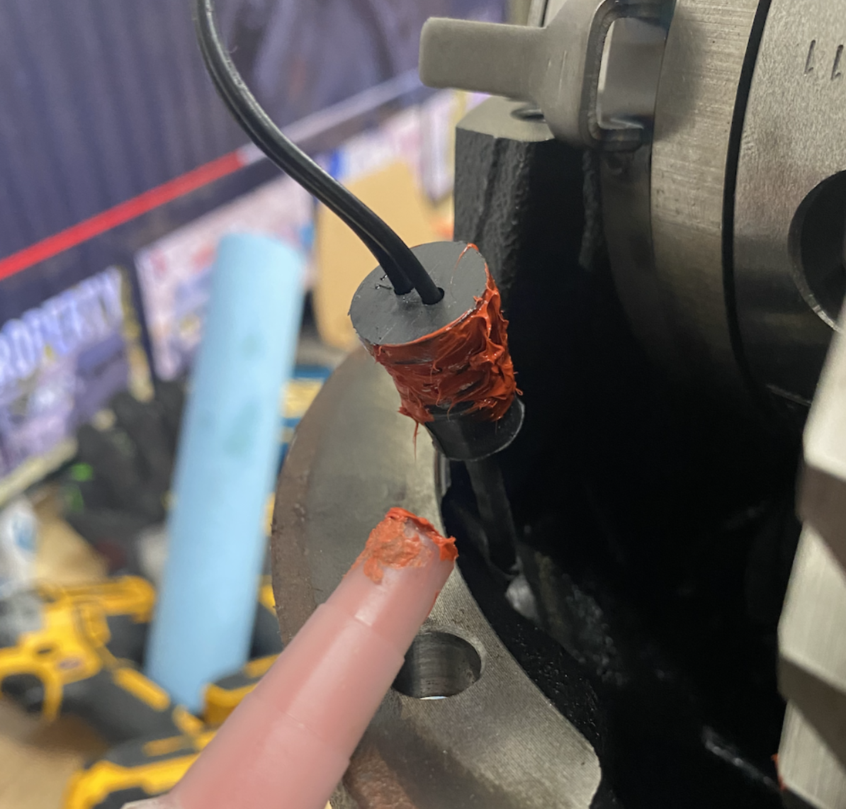
After the hole is drilled out, reinstall the differential, pull the wiring through and use some high-temperature RTV on both sides of the housing to ensure that the wiring gasket is fully waterproof and sealed.
Add your bearing caps back in making sure they are in the original orientation and torque down the four bolts to 76ft lb. At this point you will want to take another set of ring gear run out readings with the dial indicator to ensure it has stayed within range after everything was tightened to spec. Repeat the previous steps to do this.
If everything looks good it’s time to check the contact pattern of the ring and pinion gears. This is probably an optional step since in theory, we didn’t change the pinion depth. However, better safe than sorry I say! Add some gear marking compound to your ring gear and rotate the gears a couple of revolutions both ways while putting some tension on the gears with a pry bar. Here is a handy video on how to do this.

Your contact pattern should look something like the image in the center both on the drive and coast side.

Step 8. Reassemble Axle Components
Before reinstalling the third member to the axle, you will need to clean out the old gasket and install the new OEM seal that you bought. A razor blade is going to be your friend here.

Once the new seal is in, reinstall the third member onto the axle housing. Using a 14mm socket torque down the housing nuts to 38ft lb.
Now it’s time to put everything back together again:
- Axle Shafts – Carefully push back in the axle shafts so they engage with the new differential splines. Torque down the four axle housing bolts to 44ft lb on each side with a 17mm socket
- Brake Lines – Reinsert the rear hub brake line retaining tabs on both sides of the axle. Reattach the brake lines to the axle housing using a 12mm socket. Torque bolts down to 9ft lb
- ABS Speed Sensor – Plug the ABS sensors back in on each side
- Rear Sway Bar – Reattach the sway bar to the axle and frame, torque the axle bolts to 33ft lb and the end link bolts to 11ft lb
- Propellor Shaft – Reattach the propellor shaft making sure it is in the correct orientation using a 14mm socket and wrench and torque bolts down to 65ft lb.
- Refill Differential Fluid – Refill you differential with gear oil following the procedure outlined in this article
Step 9. Wiring Everything Up
Ok we are in the home stretch here. It’s time to do everyone’s favorite thing to do, wiring! The Eaton kit comes with a male plug that you can attach to the wiring pigtail coming out of your differential housing. The orientation of those two connectors doesn’t matter from my understanding so just plug them into the plug.

Once that is done get some 1” wiring loom on the main wiring harness and pull it through the engine bay back to the rear differential. I routed mine through the driver side of the engine bay and rode the driver side frame rail back over to the fuel tank as illustrated in these pictures. Make sure that there is enough slack to allow for axle movement and that the wiring clears the propeller shaft as it moves around. Connect the main wiring harness with the axle plug.


The main wiring harness is split into several different components displayed below. At this point most of your wiring harness should be sitting in the driver side of your engine bay.

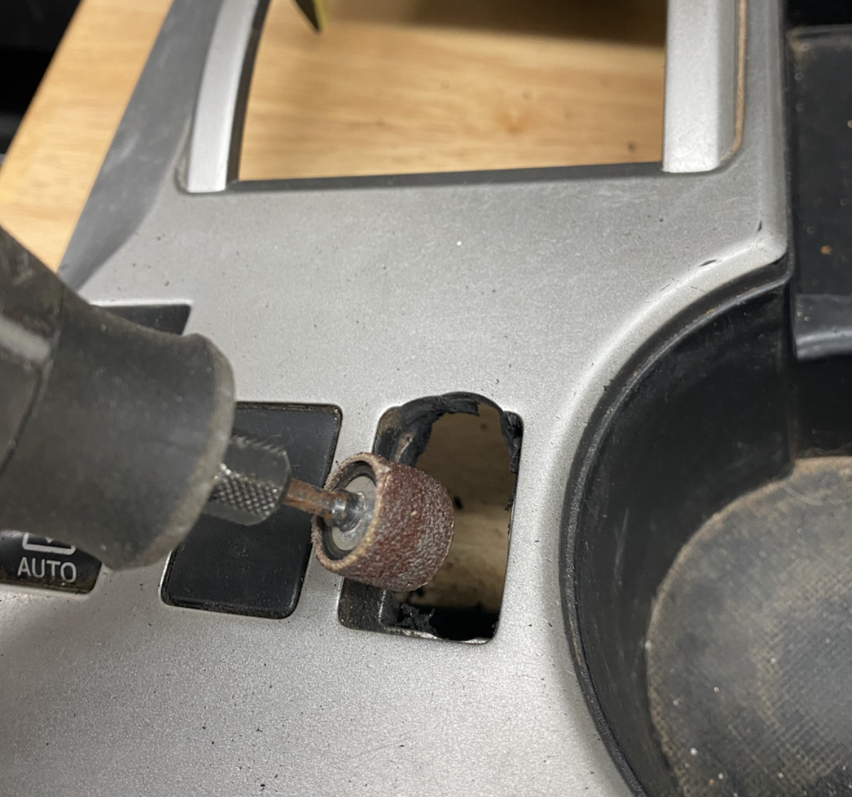
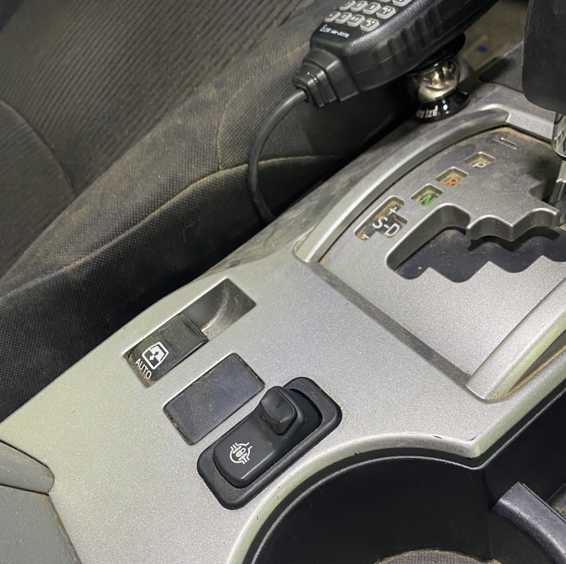
Once the main harness is pulled back to the rear axle you can start working on wiring up the activation switch. I chose to mount the switch on my center console since I had two blank plates available and I wanted the future option of adding a front locker switch if I decided to go that route. The switch itself has a safety mechanism that would prevent accidental activation so I wasn’t worried about the location too much.
Remove the center console trim and take a dremel to widen the blank plate so the button sits snug and in the correct orientation in the hole.
You will also need to remove a little bit of your transmission stalk housing’s trim to provide clearance as noted in the picture here.

I didn’t capture a ton of other photos after this point because everything else was pretty standard when it comes to wiring. So I will try to describe subsequent steps in detail.
- Ground Switch Wiring – There are a few bolts readily available in the transmission tunnel that make great grounding points
- Fuse Tap – Run the blue wire from the switch to your driver side cab fuse box. You want to choose a fuse that is only powered when the ignition is on. Use the included fuse tap
- Signal Circuit – You need to run the yellow signal circuit wire from the switch to the main harness in the engine bay. I used the driver side firewall grommet to run the wiring through. Join the yellow switch cable to the yellow main harness cable
- Main Harness Power – The main harness has an included 15 amp breaker which will need to be wired to your positive terminal of your battery
- Main Harness Ground – Ground the harness using any of the readily available chassis bolts in the driver side front engine bay
I’ll update this article with a picture of the final engine bay setup once I clean it up. Right now it’s not up to my wiring standards so I will spend a weekend addressing it. The final in-cab setup worked out pretty well I would say. It pretty much looks OEM.
Step 10. Get Out There and Test This Thing
After wrapping everything up I took the truck out for a quick parking lot test to see if I could engage and disengage the locker. I was able to hear the unmistakable chirping of tires when I turned the locker on and slowly rounded a turn. So I knew it was definitely working. The next day I drove out to our local off road park and put the truck through its paces and immediately noticed a huge difference when climbing trickier obstacles.
I should have installed this thing earlier!


Eaton doesn’t explicitly say this but it is probably a good idea to change your differential fluid after 500 or so miles to be safe. Since I reused my OEM ring and pinion gears nothing should be really breaking in but better safe than sorry!
That’s it, enjoy your new locker and extra off-road capabilities. Happy Trails!
My 4R already has a rear locker but I read this entire thing after finding it because it was so freaking well written. I learned a lot! Thanks for taking the time to do this!
This post is impressive, but your bike rack really catches my eye. I have the same rear bumper… could you please elaborate on how you put a rack like that on your 4R? Thanks in advance!
Sorry didnt see this until now. I just had CBI weld a receiver on the tire swing out. Best upgrade ever as I can transport bikes over really technical terrain with ease. You probably could do this after the fact too
Hey Pete, thanks for taking the time to do this awesome write up. I was curious as to where you got your shims? Did you use use oem or an aftermarket kit? Would like to know what you used as I prepare to do this mod. Thanks!
In case anyone needs to find shims, I used the Motiv SK47 kit and it worked fine for me. I used every shim in the pack and measured my backlash at 4.7 to 5.0 (spec is generally 4 to 7) for the 5th gen. Shim dimensions ID 2.73″ and OD is 3.28″. Good luck.
Also wondering how its holding up? Any issues so far?
Holding up great 3 yrs later, even put it through the Rubicon and other hard trails. Works like a charm.
Im wondering if you know anywhere in CO that has done this upgrade from an SR5? Ive been hearing shops say they do the ARB air locker but Im not interested in that
Phenomenal write up! I’m wondering how a helical style diff would perform. Not quite as well rock crawling, but better for snow and such as it’s on all the time. Also no wiring would be nice
this site is a gold mine Man cant thank you enough. JailBreak Overlander
Thanks Richie, I’m a big fan of your Youtube channel. Let me know if you have any questions on the install!
Hey Pete, wanted to check in and see how it’s been since the install. And I don’t know if I missed it but did you regear as well or just do the locker?
Hi Nathan, I didn’t regear out of laziness. However, I may do that pretty soon and also add a front elocker as well. Ill be sure to write up an article on that if that happens. The new locker has worked fantastically. I’ve done some pretty gnarly trails with it like Slickrock in CA, Metal Masher, Poison Spider Mesa, Elephant Hill in Moab and its been a nice to have all that extra traction!
What Eaton Locker is this, plan on doing the same, but have a hard time with what locker is the right one?
Ben posted the correct part #, I have updated the article to reflect this.
I have also been planning this upgrade but I have been having a hard time finding part number verification. I am assuming its this one.
https://sdhqoffroad.com/collections/toyota-4runner-drivetrain/products/e-locker-toyota-8-2-electrically-actuated-locking-rear-differential
Peter, this is so impressive. I am a lost of words. I very happy to see your hard efforts worked out so well for you.
Thanks Shaf, it was a fun project and Im glad I did it
Hats off to you for the DIY. I’ll be interested in hearing how well the Eaton works. One bonus of my ARB lockers is the on-board compressor, but that is easily added.
Thank you sir! I have taken it through its paces through its paces with three trips so far and its still working like a charm. We just did the Slick Rock trail here in CA and the locker was engaged for most of the trail. Agree on huge benefits of an ARB compressor though. The dual compressor I have under the hood is one of my favorite upgrades!
No problem. I debated doing the front locker, and wondered how often I would use it. A 27″ snow later, I was chewing up the snowplow piles in front of our driveways.