
Complete Step by Step Install of the Switch-Pros 9100 with PowerTray: How to Wire a Switch-Pros In Detail
Electrical organization will come into play for most builds, mild to wild. For some it will include a light bar and an additional USB plug, for others, it will be a whole system that can power and manage all of their electrical needs. In a lot of cases, owners will start by adding a few things here and there until their engine compartment and battery terminals look something like a rats nest of wiring and in-line fuses.
At some point enough is enough, and something must be done to harness all of those errant wires into an organized and functional system. Enter the PowerTray electrical main panel. It bolts in place on the driver’s side of the vehicle to provide a sturdy and functional platform that a variety of different electrical components can be bolted to, specifically tailored to the vehicle it is installed in.
Made with ⅛” brushed aluminum and stainless hardware, it is built to withstand the harsh environment under the hood.
This installation will be showcasing their “Switch-Pros PowerTray” which is optimized for a Switch-Pros 8100 or 9100, a Blue Sea 6-circuit fuse block, a Blue Sea 8 slot terminal block and their “stubby” cables. All of the components and the associated hardware, other than the Switch-Pro itself, can be purchased directly through the PowerTray website. The basic installation of this tray will be the same with any of their configurations.
Parts / Tools Needed
Main Switch:
- Switch-Pros SP9100: Check Price
Materials:
- Switch-Pros Vertical Mount PowerTray / hardware
- Blue Sea 6-circuit fuse block (#5025)
- Blue Sea 30A, 8 slot terminal block (#2508)
- Blue Sea 10 screw BUS bar (#2301)
- Blue Sea 100A 285-series circuit breaker (#7187)
- Shrink tubing (with adhesive), various sizes
- Battery wire and ring ends
- 3M fastener
- #10 fork terminals, marine grade
- Allen Wrenches – 3mm, 2.5mm
- Wrenches / sockets – 7mm, 8mm, ½”, ⅜”
- ⅜” Ratchet with extensions and universal joint
- Screwdriver
- Electrical Pliers
- Crimping tool
- Heat gun
- Blue Loctite
Step by Step Installation

Start by laying out your accessories on their designated cutouts, making sure that you have them all facing the correct direction. Then, using the supplied hardware, install the accessories on the tray.
The terminal block uses 4-M8 bolts/nuts, the bus bar uses 2-M8 nuts/bolts, the fuse block uses 4-M7 bolts/nuts and the Switch-Pro uses 2-M4 bolts/nuts. It’s a pretty straightforward procedure, the holes will only line up in one combination.
This will be the same with any of their pre-configured trays. The blank tray will need to be customized at this point to suit the buyer’s specific needs.
Terminal bar (left), Fuse Block (center), BUS bar (right)

Laying out the Blue Sea components

Components on the PowerTray and fastened
NOTE (02/05/2019): Switch-Pros have specified in their instructions that the SP9100 power module is designed to be installed either vertically or facing down. This is to keep moisture from building up on the wiring harness and potentially getting past the plug seals and into the corrodible connection pins. I confirmed this with a phone call to their tech support. Mounting it horizontally as instructed by PowerTrays can potentially void your Switch-Pros warranty if water causes a problem with the connections.
NOTE (o3/03/2020): PowerTrays has released an updated version of the Switch-Pros PowerTray that mounts the unit vertically along the back of the tray. This new orientation satisfies the Switch-Pros warranty disclaimer mentioned above. The new product can be found here or in the parts list above.

Wiring the Switch-Pro out of the vehicle
The Switch-Pro comes with individual leads for each of the 8 outputs it has. This can get messy in the engine bay with wires being connected and no real way to organize them.
With the use of the Blue Sea terminal block, these leads can be organized and easily arranged to suit the customer’s needs. It’s best to wire the Switch-Pro to the terminal block outside the vehicle so you aren’t leaning over the fender for an hour trying to make everything equal.
Start by separating the output leads from the input leads of the Switch-Pro, ordering them from one to eight. Start with output lead number one, cut it to length with a little extra slack for good measure.
Be sure to strip the end ¼”. Slide a ½” piece of 1/4″ shrink tubing over the wire, then use the crimping tool to secure a #10 fork terminal on the end of the wire. With the heat gun, apply heat to the terminal to seal the end.
Next, slide the shrink tubing over the cooled terminal end and apply heat to finish off the lead. Attach the lead to the designated screw on the terminal block to secure it. Repeat for leads two through eight for a clean finished product.
The Switch-Pro wiring harness plugged in

Arranging the wires by type to make arranging them easier

Wires are cut to length, shrink wrap in position

Wires are cut to length, 1/4″ shrink wrap in position, and connector crimped. Don’t use the heat gun yet until everything is test fit.
All wires test fit and in position. Everything looks ok for final fit.

Apply heat with a heat gun to the connector

Apply heat with a heat gun to the connector first, then slide the shrink wrap over the connector and apply heat again until sealed.
The final product with the Switch-Pro wires connected

Stubby or No Stubby

These are the PowerTray Stubby Cables. For my installation, I used the negative cable shown, but changed the positive cable to dedicated runs. One for the fuse block, one for the Switch-Pro.
PowerTrays offers what they call their “Stubby Cables” for this setup and essentially the kit is a set of short cables that connect the positive leads from the Switch-Pro and the fuse block together and the negative leads from the fuse block and the BUS bar. In theory, by using cables, you eliminate the need to have separate positive cables for the Switch-Pro and the fuse block leading to the battery making for a cleaner installation.
You use the provided positive cable (with 125A fuse) from the Switch-Pro to connect to the battery, and the power is then split at the Switch-Pro positive terminal to power the Blue Sea fuse block. PowerTray mentions on their website that as long as you will not be consuming more than 125A between both the Switch Pro and the fuse block, this arrangement works just fine.
However, on the Switch-Pro installation sheet at the top of page one, they note: “3. Do not connect any other power feeds to the power module’s power stud.”
With that noted, I opted to separate the positive leads so that the Switch-Pro and the fuse block would have their own battery connections. (note: photos of the initial configuration show the positive stubby cables before I switched it) I did leave the negative stubby cable connecting the fuse block and the BUS bar intact as there was no noted reason to change it. It attaches to the negative terminal on the fuse block and the closest terminal on the BUS bar using the supplied hardware for each unit.
Installing the PowerTray
Now that the tray is configured with all of its parts, loosely attach the leg to the tray using the supplied hardware and grab the two M10 bolts that will be used to attach the tray to the fender using the stock tapped holes.
First, I needed to remove my Slee Offroad compressor bracket and ARB compressor to make room for the PowerTray. Once it was removed, and the existing wires from other accessories were disconnected from the battery and pulled aside, I positioned the PowerTray.
I positioned my tray as forward as possible to allow for the most future access behind the tray to the firewall grommet, making future wiring less cumbersome. There are two slots on the tray edge facing the fender, and when positioned as forward as possible, both of the fender holes line up in the slot closest to the firewall (see photo).
You will need to configure your ratchet with extensions and a universal joint to tighten these bolts as the access underneath is limited.
Once the fender bolts are snug, you can position the support leg to align with an existing non-threaded hole in the lower wheel well sheet metal.
Here you will use the supplied bolt, washer and nut to fix the support arm to the hole. Blue Loctite should be applied to all of these bolts to reduce the risk of vibrational loosening. With that, the tray is installed.
The engine bay as it was before this upgrade

Compressor removed, and wires disconnected

Laying out hardware for the PowerTray

Laying out the hardware for the PowerTray on my platform slide out
Thread the fender bolts into positions

With the PowerTray in position, lightly thread the fender bolts into their designated positions. Be sure to use Loctite.
Note the position of the bolts

Note the position of the bolts on the back slot of the tray, allowing for the tray to be as forward as possible.
Add the support bracket

Add the support bracket and line it up with the hole in the fender. Loosely install hardware to allow for movement and alignment. Remember to add Loctite.
Bolt through fender
This shows where the bolt comes through on the other side of the fender.
Universal socket joint – tighten the bolt
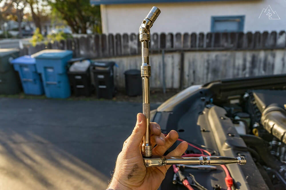
Use a universal socket joint to allow for easier tightening of the bolt.
Check for final fitment and tighten all bolts.

The installed PowerTray and components.

Wiring the Switch-Pro in the vehicle
The Switch-Pro requires a few wire inputs for proper function:
The blue wire must be connected to a source that only comes on when the vehicle is in the “ON” or “ignition” position. This tells the unit when the vehicle is on, allowing for accessories that have been programmed to be on only when the car is running to function.
The white wire connects to a source that signals the vehicle’s lights are on. This allows the control panel to dim when the lights are turned on. A handy feature at night. Both the white and blue wires can be run through the firewall to the fuse panel under the dash on the driver’s side near the emergency brake pedal. Using an Add-A-Fuse, connect the blue wire to the vacant slot fifth down from the top on the right side. This is an ignition triggered fuse. Using another Add-A-Fuse, connect the white wire with the “tail light” fuse, bottom on the left. Since the tail lights come on with both the parking lights and the headlights, this is an optimal one to use. Use 2.5A fuses for both.
The pink wire can be wired with another non-Switch-Pro switch to power a light. For example, you could wire your stock high beams to the pink lead on the Switch-Pro to control an auxiliary light bar that you would want to turn on with the high beams. I did not use this feature yet, so I zip tied the wire under the PowerTray for future use.
The black wire is the negative lead that should be wired to the negative terminal of the battery or in my case, the negative BUS bar on the PowerTray.
Finally, the red power lead gets connected from the stud terminal on the Switch-Pro unit to the positive terminal of the battery. I was able to route mine under the PowerTray for a clean appearance while still being able to access the fuse if needed.
Add-a-fuse

The add-a-fuses connected to the blue and white wires from the Switch-Pro, powered at the fuse panel on the driver’s side.
OEM fuse panel

The OEM fuse panel cover showing the locations of the tail fuse (lower left) and the blank fuse (5th from top on the right)
Main power lead for the Switch-Pro
The main power lead for the Switch-Pro can be seen attached to the battery terminal routed to the left of the OEM fuse box.
The Switch-Pro Control Panel
Where you wire the Switch-Pro control panel, it’s entirely up to the user. For me the key factor for the location was simple. I wanted to have the panel in sight but out of sight, meaning I wanted them to be a quick glance from the road or trail, but not in my face to distract me when I am not looking at them.
I wanted them to be in a “natural reflex” zone in the same way that your high beams are so that I can quickly turn accessories on or off without having to look for the switch. I wanted to have it out of the way so that I don’t compromise usable space in the vehicle. And lastly, I wanted to have it as discreet as possible because there are enough reasons for someone to break into a vehicle as it is.
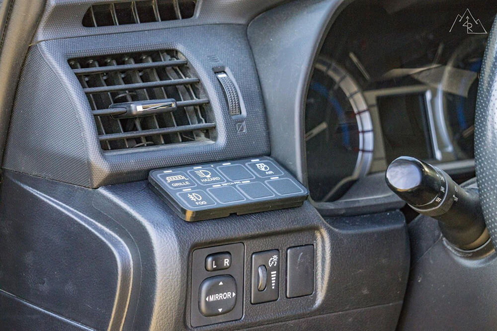
With all of those factors in mind, I chose to mount the control panel below the leftmost dash vent on a panel that fits the unit perfectly. I mounted mine directly using the supplied hardware, and the supplied drill template. A step drill bit will allow for a clean hole in the OEM trim panel.
SDHQ does sell a replacement trim panel that has the Switch-Pro cut out, allowing it to mount completely flush. I was okay with saving a little extra mod money and having a not so flush (but pretty darn close) finish.
The last step is installing the stickers that correspond to your chosen accessories from the sticker sheets that they provide. Make sure to use the blacked out blanks for any unused switches to keep the backlight from being exposed and too bright to the eye.
Following the Switch-Pro instructions, remove the plug coming from the Switch-Pro unit, and pass the wires through the firewall grommet. Once on the other side, reinstall the plug end and attach it to the control panel plug, securing the wire with zip ties.
The Shelf on 4Runner

This “shelf” above the mirror controls is where the control panel will be installed.
Template provided by Switch-Pro

Using the template provided by Switch-Pro to line up where the panel will be installed.
Remove the panel for drilling

It’s easier to remove the panel for drilling than to do it in the vehicle. You are less likely to nick another panel.
Switch-Pro panel installed – no labels

The Switch-Pro panel installed without the labels installed.
Final installation including labels

Wiring the Fuse Block and BUS bar
To complete the circuit for the auxiliary power on the PowerTray, you will need to connect to a positive and negative source. First, you must choose how you would like to isolate your auxiliary power.
The two most common ways are using a fuse which when overloaded will blow and must be replaced. The other option is using a circuit breaker, which will also blow when overloaded but can be reset once the overload is isolated and fixed.
I decided to install the breaker to allow for an easy disconnect if I need to work on the electrical system, as well as it makes field fixes easier because you don’t need to bring a spare fuse. I installed the breaker a short distance from the battery terminal, attaching it to the top of the OEM fuse block with a strip of 3M fastener.
Using an appropriately sized wire, I cut and attached two eyelets to create the positive lead from the breaker to the stud on the fuse block. I used red shrink wrap on the ends to show that it is a positive lead. I used the same wire for the negative connection, attaching it to the stud terminal on the BUS bar on one side and the negative battery terminal on the other.
It’s always best to ground to the battery directly when possible because not all “body grounds” can guarantee a good ground.
Blue Sea circuit breaker

The Blue Sea circuit breaker for the fuse panel attached to the OEM fuse lid using 3M fasteners.
BUS bar to the negative terminal on the battery
Note the black negative wire attaching the negative BUS bar to the negative terminal on the battery.
The Results

With that, your installation is done. You can now connect your switched accessories to the Switch-Pro and your constant supply accessories to the fuse block using the same wiring techniques as when you wired the Switch-Pro leads in the beginning and appropriate fuses on the fuse block. Enjoy the cleanliness of the engine bay as you power all of your vehicle add-ons in style.
Love the blue sea parts!
FYI – Switch-Pros explicitly says not to install the panel with the wires facing up like this. I’d highly suggest installing the switch-pros control panel on the underside so the wires face down. Adding another slot between the control panel and the buss will give a much cleaner install as well.
Obsessed with the cleanliness and organization of this mod. Only hiccup I’m running into is finding out what lengths and what quantity of the stubby cables to order from power trays. Didn’t find any specifications in this write up and help would be greatly appreciated! This is my first wiring/electrical job on my 4Runner but have worked some electrical before.
check out sdoffroadmt on Instagram. He makes kits with everything needed and wires pre cut for this install. His newest version even allows for a ARB twin compressor. He’s a solid human being as well.
Okay I see now they sell vehicle specific kits
How did you decide that the add-a-fuse needed 2.5A fuses?
Max, I had a question on the positive battery cables running from the fuse block positive distribution block to the Switch Pro, and seemingly a 1ft positive battery cable from the same positive distribution bus to the circuit breaker. Is this correct? Therefore, we would have the lugs for both positive battery cables stacked on top of each other?
Technically you should be connecting the Switch-Pros Power Cable directly to the battery with their cable. Not through some other Circuit Breaker. This is per their instructions and they are very clear about the situation.
You can actually see he changed it to direct. The red power wire with no black covering goes from the Switch Pro to a shunt and then directly to the batter positive terminal, rather than what’s shown in the 12th picture.
This is fantastic. I just ordered the parts to do this on my FJ Cruiser. I was wondering if you know if Blue Sea makes a terminal block cover to protect it from rainwater? If not, do you have any strategies for protecting the exposed components from water? I may be installing hood louvers in the near future, and so I would like to prevent direct water contact if possible. I think it would only matter when the vehicle were parked, so probably rigging up some sort of deflector between the louver and the panel would suffice.
Thank you for the write up! For 2020+ owners, do take note that the fuse orientation is a little different. Also, do read up on how add-circuits / add-fuses work. Understand that there is a load side and a draw side. I made the mistake of not researching how it works and ended up creating a short and blowing a relay. The weird part is that it didn’t blow any fuses whatsoever but I lost Tail lights + interior Instrument Panel lights. I had zero power going to the fuse box itself on Tail and Panel. The real kicker is that the relay is an internal relay controller that is built inside the fuse box component. Sitting at the dealership now as they replace the unit. Don’t make my mistake!
Hey, I followed your install pretty much line for line, my only issued comes with the blue wire for ignition power being tapped into the add-a-fuse. I have my unit exactly as you suggested, but am only able to control my unit under BT control, I have all switches set to ignition control and get no backlighting or switch use unless i use the app. I still get by backlighting adjustments when my lights are turned on, and I am seeing 12+V via the app. Do you have any other suggestions for ignition powered fuses that can be tapped into?
Hey Jay // I would first check that your fuse in the add-a-fuse is in the correct position (slot closest to the wire). If that’s unsuccessful, place the add-a-fuse onto the P/OUTLET fuse as it’s an ignition only circuit used to power the 12v circuits inside. // Max
Thank you! I’ve been trying to figure this out since install. (Thank you for the indepth guide, by the way!) I attached a picture for posterity, hope you guys like my custom spark-EE plate!
At first I assumed it was a BT necessary device, which was a bit odd. Then I dug into the settings pretty deep, then I dug into too many forum posts and fuse box diagrams.
I’ve gone back and forth with their customer service for days on end, and in under 24hrs you were able to give me the best advice yet, took all of 3 minutes to get it working this morning!
Heya 2020+ owners, just wanted to let you know that we’ve got a really slick workaround for that relay box. Just unbolt it and move it closer to the firewall. I made a mini writeup if you want more info.
https://www.powertrays.com/pages/2020-4runner-relay-box-relocation
Hey, I’m a bit lost here. I looking forward to have kind of the same set up on my 4R, but I’m going with the single arb compressor tray. The thing is I can’t figure all the wiring connections. Like what goes where? Let’s say I have a new accessory, the negative goes to the bus bar and the positive to the fuse block and from that fuse block then I’m going to the terminal block that is finally connected to the SP? Or should I have the positive wire from my accessory to the terminal block but then what end up going to the fuse box?
Hey Robert just seen this and you’ve probably figured it out by now but for other readers members here, the fuse block has nothing to do with the Switch-Pros… For wiring things to your Switch-Pros you’ll just attach the positive to the terminal block and the negative to the bus bar. The fuse block gives you the ability to wire up things the old fashion way.
Hi Max,
where did you get the short battery cables and in what length?
Thanks for the review! It helped me a lot.
John // The short battery cables were from Power Tray. I believe it’s their “Stubby Kit”
Did you leave terminal connectors with positive voltage exposed?
Christopher // Yes, they are exposed. I don’t have an issue with this as there is a very very low chance of an electrical short in this setup. And it would only short back to the Switch Pro which has a built in amperage breaker that would cut power in the event of a short almost instantly. // Max
To all 2020 owners who happen to read this great write up by Max…
So, there are few things different on the 20’s like making sure you get the right PT. I assumed the 2019 PT I ordered off their website would fit. But, I should have confirmed before my purchase. They do make one for the 2020+ model to accommodate the extra OEM fusebox assembly. The other is the add-a-fuse placement. I initially installed two like Max said in his article in appropriate places.
However…
For some reason my white wire add to the fusebox (in the tail and then in the LP light positions) gave the system a series of gremlins… error codes on the panel and randomly turning on lights after I had parked and left the rig unattended.
I reached out to Switch-Pros and they responded quickly via email (on a Saturday!) and asked I call I’m on a weekday for the best service.
In the meantime, I started from scratch, reinstalling all the wiring and this time took the white wire and tapped it into the front driver’s parking light. That worked well but then the BT light was on showing I had a consistent Bluetooth connection. And now the BT wasn’t working on my iPhone. Ugh.
Solution? Disconnect both ground and positive from the system and let it sit for about a minute.
Fingers crossed… all is good!
New to auto wiring. How would this system fit into the diagram I’ve shared?

It all depends on if you have a Switch Pro to power your lights. The diagram that you have shown there has a standard relay being used to power the light from the battery, triggered with a standard switch. How are you planning to switch your lights on and off?
All-
Has anyone installed the updated tray on a 2020 model yet? There is a new (?) relay fuse box taking up the mounting holes for the tray. Looks like it’ll make a challenge to get it in there. Just wondering if anyone has come up with a solution.
Trail Safe.
-JB
I used the ARB compressor mount from RAGO and had to modify the fuse block under the mounting plate in order for it to fit right. Came out great but I’m glad there’s others out there. Here’s the link to my page for ref. The plan is to eventually add either the SPOD or Switch Pros unit.
https://www.4runners.com/threads/2020-t4r-offroad-premium-w-kdss-my-first-toy.14015/
yes, contact sdoffroad@hotmail.com and/or check this install on t4r
https://www.toyota-4runner.org/5th-gen-t4rs/286893-sd-offroad-switchpro-9100-mount-tray-2020-a.html
Available is the Fuse and Terminal Block MOUNT TRAY for the 2020 4Runner
MAN that is frustrating… to see this offering after doing the PT install. BUT great for other 2020 owners. Thanks for posting!
Trail Safe
JB
Sorry JB, I get it… I had posted down lower similar information and there’s a write-up on trail4runner about the Vertical Mount. I will make sure there’s a post at the bottom making sure people know there’s a 2020.
I figured something out and fab’ed a mount out of Hillman pre-drilled steel. (Get it at Lowe’s or Home Depot) The trick is to take your time to make the right bends. Since your raising the tray to clear the fuse box, you need to have a slight offset to ensure the hood strut doesn’t hit the Switch-Pros when you shut the hood.
Any finished product pictures? I have a 2020 and my vertical mount power tray is on the way.
Adam-
I knew I shouldn’t have left the 2020 owners hanging! And I probably should have written up something for T4R. At any rate, I can apparently post only one picture per discussion, so here you go. Look closley and you can see on the leg I made some 90 degree bends on the Hillman strap and once I was happy with it, I painted it with some gray Rustoleum.
Looks good J.B.! Thanks for the visual/idea. I am sure this will help many other 2020 owners out there!
Yes sir! Hopefully PowerTray will get another tray in the mix for the 2020’s. But I am happy with my work around. (I probably need to do a write up for T4R on this, but that means I’d have to take it all apart again!)
Speaking of…”pro tip” mock up the mount FIRST on this before you assemble the SP and all it’s wiring. I did initially and had to disassemble it to get everything lined up.
J.B.
Thanks for the tip! I’ll share my experience in a week or so when mine arrives and it’s installed.
Where did you move the Compressor?
I moved it to the passenger side using a 4×4 Labs mount // Max
My dawg
Hey Max – For the Add-a-Fuse going into the vacant slot (ignition controlled), do you just use a 2.5A in the additional fuse slot or do you have to put a fuse in each of the slots?
Nevermind, I figured that one out myself. On another note, the empty slot you use for the ignition controlled circuit isn’t there on the 2020’s. The only open circuit is always on. So, I added mine to the outlet circuit, which is ignition controlled.
Chuck,
Which circuits did you had your add-a-fuse? I’ve been struggling with this for a week and can’t figure it out.
Sorry, I didn’t see this right away….for the power, I used the ‘P/Outlet’ circuit – a 15A circuit that’s located in the bottom right corner if you’re ready the cover. For lighting, I used the Tail Light circuit.
If you look at the cover of the fuse panel, look for the one that notes “Outlet”
Interesting, that’s good information! Thank you, and I am glad you figured it out!
Max, thanks for the write-up! Looks like everything went the way it should’ve, however, all i had access to was 2amp fuses vice 2.5. So far i can only get the accessories to work when its connected to bluetooth. Backlights come on when its not connected and I push the button for either accessory, but the accessories don’t turn on. Perhaps do i need to bump up to the 2.5? Is it something i need to program thru the app? Thanks
Hm. The 2amp fuse should be more than enough. All it’s doing it telling the Switch Pros unit that it has power from the vehicle. There is little to no load. I would contact Switch Pros about your issue with not being able to turn on/off accessories from the physical panel. // Max
Power Trays now makes a power tray for the 4Runner that mounts the Switch Pro in a vertical orientation, protecting the warranty.
https://www.powertrays.com/collections/powertrays/products/vertical-mount-switch-pros-powertray-4runner-fj-cruiser-gx-470
Among other vertical mounting options as well
https://trail4runner.com/2019/08/16/vertical-mount-switch-pros-sp9100-install/
Yep, lots of options available!
Thanks for adding this, Chuck. I have been meaning to update this information on the article. I’ll make an edit now. I only wish they offered this when I originally bought it. Maybe it’s time for a swap out!
Thanks for the write-up, Max. I connected the white wire with an add-a-fuse to the fuse location you did but it’s giving me issues. Is there a certain combo of fuses I need to use? Depending on the fuse combo one of 3 things happens: 1. The panel doesn’t dim when the lights come on. 2. The panel is dim when the lights are off and bright when the lights are on. 3. It works properly but then the panel backlight doesn’t shut off when the car is turned off. Any ideas what I could be missing?
Thanks for your help!
Hi Max,
Love your 4runner. I follow your build on t4r.org and might have taken some ques from you on mine. 😉
Quick question, did you have any issues with the back lighting on the switch panel not functioning correctly with your blue and white wires on the fuses you noted above? I connected it the same way (lt blue to 5th fuse down on the right and white to the tail light fuse on the bottom left) and noticed my panel doesn’t light up when first turning on the lights. I have to hit one of the switches first and then it illuminates and stays illuminated until the lights are turned off. I am waiting on a response from switchpro direct but wanted to check to see if you had any issues.
Keep up the great work!
Make sure for the add-a-fuse that you have 2 fuses in there. One for the existing fuse, and one for the new connection.
I’m having the exact same issue!
Make sure for the add-a-fuse that you have 2 fuses in there. One for the existing fuse, and one for the new connection.
Max,
I am trying to link into the high beams for a light bar. I can not find any information of the best way to do this for a 5th gen. I found an old post for a 2013 saying the high beams are actuated with a negative and you have to use a replay to convert. But that is it. I posted on the forum and nothing. Thanks!!
Did the install with the PT for the single ARB compressor, whew! Not easy but done.
Hey! Glad to see another T4R.org handle here 🙂 As for the light bar connecting to the high beam circuit, it does look like the OEM circuit uses a negative trigger to control the high beam relay. It’s a bit complicated honestly, and personally I’d leave them separated. You might want to run the light bar alone, which won’t be possible with them connected to the high beams. Similarly, you can still use your stock high beams separate of the light bar if all you’re doing it “flashing” someone to indicate something to them (like “go ahead” at an intersection) without having the extra blinding power of the light bar. And if you have the Switch Pro mounted in the position on the left side of the steering wheel, operating it like a high beam is really simple once you have memorized the switch location on the panel, which for me is top left (switch 1). If you do want to use the high beam as a trigger, you’ll need to tap into the harness somewhere where the only power being sent through is coming from the high beam switch itself since the DRL uses the same wiring from the fuse box to the high beam bulb at a lower voltage. Tapping in near the bulb itself could trigger the light bar if the DRL are on. Just something to consider, hope that helps. // Max
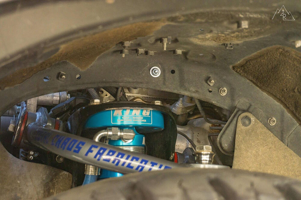
Any issues with the PowerTray rubbing on those vacuum hoses? Putting mine in now and thinking about putting a little abrasion resistant braiding over them if they’re going to be in contact there.
A little slow to reply, but no issues for me as of now…
Brackets
https://sdhqoffroad.com/collections/03-current-toyota-4runner-sdhq-built-products/products/14-current-4runner-20-behind-the-grille-top-mount-kit
So I’m just starting to mod my 2018 TRD and I’m going to eventually add lights (roof, bumper, rock) and upgrade the stereo. Should I add the tray prior to the stereo to add a mounting point for the amplifier in line fuse?
Charlie // That is going to depend on where you mount your amplifier and what fuses it will require? To my knowledge, most amp in line fuses don’t require a bracket, but it all depends on what your amp specifies. // Max
You should read his build thread. Some really creative ideas. Grab a beer or 3 and enjoy.
https://www.toyota-4runner.org/5th-gen-t4rs/209558-building-driving-adventuring-mtn4rnr.html
He is running a BaJa 20” S8, his build thread has a link.
SDHQ also makes some slotted brackets. May make is slightly easier for this application
Hi Max,
love this post my dude! just wondering what LED bar your are running and how you mounted it. i dont want to block my radiator where most put the LED bar (on the middle part) and love where you mounted it on the top part of the grille.
Thanks!
Meeks // I am running a Baja Designs 20″ S8 light bar. This requires little to no modification by bolting it to the outer grille support. Baja Designs sells a mounting kit that fits 2 10″ S8 light bars in the same place, fitting around the Toyota emblem. // Max
Thanks Max. It was just a little bit of a shock to see those warnings and not see them on the Switch Pros sight. If I still had access to a machine shop I would slot the mounting holes on the Power Trays, add a cut and bend up the mount location for the Switch Pros to let water run off a little better. The concern is that they added this, so they must be seeing some issues.
Snow Yeti // I’m guessing you meant on the Power Trays sight. Apparently they are aware of the warnings in the instructions, according to Switch Pros. That’s what I am thinking might be the final solution, or something bolt on. // Max
Just received my Power Tray and my Switch Pros. Should I be concerned that the first instructions for the Switch Pros says to ONLY mount it vertically or it may void the warranty. Then it says using a terminal block IS NOT RECOMMENDED due to water?
Hey SnowYeti / See my post in the comment above regarding the mounting orientation. They have stated that vertical or angled orientation is recommended. I have sent an email to PowerTrays to get their side of it, and if anything can be done from a product stand point to match the Switch Pros recommendation. As for the terminal block, I don’t have an official opinion or explanation from Switch Pros or PowerTrays directly. My take on it is that they are trying to prevent moisture from accumulating on connections and corroding them pr the wire leads out. Seeing as that area of the engine bay should never really see any direct water, I am not very concerned about it myself. The leads coming from the Switch Pros harness are all connected to the fork connectors with dielectric grease and marine shrink wrap. All I keep an eye on is signs of corrosion on the connectors themselves, because they will corrode visibly way before any wiring is affected. Hope that helps. / Max
Hi, switch pros manual says very specifically to mount the control module vertically. Is the powertray still an acceptable way to mount it?
After speaking with Switch-Pros directly, they stand behind their instructions with mounting it vertically or facing down to keep water out of the connectors. Their connectors are as high-grade as possible, however in some scenarios they have seen water get past the seals, corroding the connector pins. I have updated the article above with a note to reflect this. // Max
Good call on the vertical mounting recommendation! I saw the caveat in the article above.
Now, the big questions: (🥁 please)
1) Would you keep it mounted horizontally or change it up to the manufacturer’s recommendation?
2) If you did change it up, would you still use the Power Tray or go another route?
3) If you did you see the Power Tray to mount it vertically, what’s the best way of making it work?
I still have mine in the box and am hoping to “do it right” the first time. I know, I know, wishful thinking, right?
1) I personally will keep it mounted as-is, unless PowerTrays comes out with a modified mount. That area of the engine bay doesn’t and shouldn’t see water directly, so I am less concerned about it.
2) I would use the PowerTray, and just modify it to adjust the angle.
3) I would imagine that installing a 45º to 90º bracket to the PowerTray in the same location would be the simplest way to do it, and likely the way I’ll go if needed.
Good news is that if you want to change things up to adjust the angle later, you won’t be going backwards by purchasing the PowerTray. Pretty much every 4Runner specific mount has a flat mounting position for the Switch Pro, except the one that comes with your Switch Pro in the box. If I get more information from either companies, I will update the comments and the article. / Max
Jean-Yves // I reviewed the installation instructions and their verbiage is as follows: “Mount the power module in a vertical position, so that water can’t accumulate on the connector seals. Failure to do so may result in limited or no warranty coverage.” Now, my guess is that they are using this blanket statement to cover every application, including exposed chassis off-road vehicles where water intrusion is much more common. Where it’s located on the Power Tray in the 4Runner, it is very unlikely that it will encounter water in the way that they have described, so I don’t worry about it. I did call them this morning to clarify, but I think they may be out at KOH like many other off-road companies this week. If I hear from them, I’ll update this comment. // Max
Assuming the loads are below the max for a circuit on the Switch-Pro, can you run things like lightbars directly off of the output from the Switch-Pro or would it be best to have a fuse between the device and the Switch-Pro?
Hi Mike — Yes you can. LED lights in general have a low amp draw. Even Baja Designs LP9 forward lights are only 7.6A per light. The “fusing” is done internally, and if you exceed the amp rating per circuit the Switch Pro will shut off to protect the rest of the system. SO, no need for an additional fuse until you exceed the amp rating of the circuit. Then you will want a relay to manage the power more directly — Max
Max, I just read a post on 4runner.org titled “Own a Baja Designs Pocket Kit Pics Please” where you mentioned that you have the ability of decreasing the intensity of the amber fog lights using a long press on switch pro control panel. I had the Pros and that was really bright so I returned them and got the Sports at half the lumens. Now I am thinking of going back to the Pros. This 9100 install tutorial is excellent to follow but it still seems like too much for me still. Do you have figures that reference the lumens difference you get for the Pros? Also does the power wired form the fog lights go directly to the 9100 and the existing OEM socket just gets taped up and not used?
Hi Shaf — The installation itself really isn’t too complicated. However having knowledge in proper wiring technique (shrink wrap connectors, wire shielding, etc) definitely helps. The Switch Pro will allow for dimming in increments of 100%, 70%, 50%, 30%, and 10%. At 4,900 lumens each, well… you can do the math! As for the power, with the Switch Pro installed they are wired directly to it, bypassing the OEM connectors and switch. Hope that helps! — Max
Thank you for the write up, I used this to install my switchpro and without it I wouldn’t have known where to begin! One addition I would like to add that will make this the most complete package possible is the ’10-Current 4Runner SDHQ Built Switch Pros Keypad Mounting System (link below). This is a pre fabricated part for the same location you have that is the cleanest way to insert the control panel. I had a friend CNC cut it which came close but from experience this is by far the best way to mount it. Hope this helps refine the switchpro build page, glad to continue spreading the knowledge like you did for me!
SwitchPros Keypad Mount
Hey Alex! Thanks for the note. I did mention in the article that SDHQ makes a custom panel for the Switch Pro control pad, but I will add in the link to make it easier for people to find! I didn’t install it because I wanted to show what it would look like using the provided template, and because I didn’t want to spend the extra cash. — Max
I do see it now that you mentioned it, I must have overlooked it when I was getting it in there. I do agree with your response that just adding it in the top list would resolve the issue. Thanks again great write up.
Love the detailed installation. Question for you, so do you have a power coming from the blue sea fuse box to the switch pros and on top of that another power coming from the battery? (basically asking if you have 2 power supplies coming into the switch pros screwed in on top of each other).
Hi Wade — The Switch Pro and Blue Sea fuse blocks have separate power cables coming from the battery. The Power Tray instructions tell you that you can piggy back them together, but the Switch Pro instructions say that the power source must be a direct battery connection. So I went with the Switch Pro instructions and separated them for good measure.
question which area did you route the wires for the switch through the firewall?
There is one major OEM loom that goes through the firewall on the driver’s side. You can penetrate the outer portion of the rubber boot with a small knife and run the loop through there. You will need to look under the dash to see it on the other side.
Thank you for the excellent write up.
I’m in the middle of sourcing my own version but will be mounting my ARB compressor on the PowerTray designed for that
My question is with your compressor wiring; did you wire the pump switch and power through the Switch-Pros or did you keep the ARB relay for power and run the switch portion only through the 9100? Also, it would be great to see the compressor in its new location.
Thanks in advance.
The ARB relay is used along with their wiring and in-line fuse connected straight to the battery. The Switch Pro just controls the switch input for the ARB relay.
You can head to this link to see the air compressor in its current location!
Hi Max
Excellent write-up!
One basic question: is the fuse box necessary for this install? do you run the outputs from the SP9100 through the fuse box and then to the accessory (like a light bar etc)?
Hey! You don’t need to have the fuse block if your only power requirements are met using the Switch Pro. My fuse block powers things that are always powered like my HAM radio, fridge, and additional USB outlets. It all depends on what you need to power.
Hey Max,
Excellent write-up!
One basic question: is it really necessary to add the fuse box for this install? Do you still route the SP9100 outputs to the fuse box and then to the light bar/other accessories?
So when adding accessories, I’m assuming that the positive wire goes to the terminal block, and the negative to the bus bar.
Did you use forked terminal connectors or ring? I’m planning to do the accessories with weather pack connectors
Can you do this setup if you use the Slee mount for the ARB twin compressor?
Part #SOK004
https://sleeoffroad.com/product-category/air-up/
Unfortunately, you can’t. That is the bracket I had in there before and I had to replace it when I installed the power tray. I switched to the 4×4 Labs passenger side compressor mount, as shown in the photos.
Max,
Did you have any issues with the power tray panel hitting the little hub/bump out right above the threaded holes to attach the panel too? I’m not using a powertray panel but a pelfrybilt panel and am having it contact the hump before it sits flush against the metal.
Nothing that would make a significant difference. You can add washers between your mounting bracket and the inner fender well to make up the difference, allowing for a flush mount.
You mention 2.5amp fuses for both add a circuits, is that a typo do you mean 7.5amp fuses?
I should clarify, for the ignition add-a-fuse, I used a 2.5A fuse to supply input to the Switch Pro. For the light input (white wire), the fuse for the tail lights is still the original 10A, and the fuse supplying input to the Switch Pro again is a 2.5A fuse. Because the draw on both of the Switch Pro inputs is so minimal, you want to use the smallest fuse you can to make sure that anything causing even a small increase in load (short, etc) will trip the fuse before shorting anything else in the OEM fuse block.
Max, how the hell did you get the cable for the sp9100 through the fire wall?!? I can’t seem to find out how to release the pins to get the connector off?!
Hunter, In the instruction manual for the Switch Pro there are instructions for how to remove the plastic end from the wires so you can just run the wires through the firewall. Best to send a fisher wire through first and then pull back with the Switch Pro loom attached. Check page 3 of your instructions.
YES what Eric said, Love the write up! im going to do the same thing!
Hunter, part numbers have been updated and I have provided links where applicable. Feel free to respond with any questions you have. Happy mod’ing!
what do you have attached to your fuse box?
Currently I have my HAM radio, and a few lights with their own switches. In the next few weeks I will be adding fridge power as well as a few dedicated USB power outlets that are independent of the ignition for charging when the vehicle is off.
Eric, I’ll update the original post with that information later today / tonight!
Few questions:
1. What’s the diameter for the shrink tubes? Can you provide a link?
2. Which circuit breaker did you use? What’s the part number?
3. Can you provide a detailed part number list?
Eric, part numbers have been updated and I have provided links where applicable. Hope that helps. Happy mod’ing!
thank you sir!
this is really helpful!