
Looking For a Cheaper Switch-Pros & sPOD Alternative Off-Road Switch Panel? Start with this 6-Circuit Switch: Full Step by Step DIY
Wiring lights and other accessories in your build is really simple at first.
You start by adding a light here and there, then maybe another powered accessory and then it happens. The rats’ nest of wires starts to pile up at each battery terminal. After a few accessories, your entire engine bay is covered in black and red wires in all directions that make absolutely no logical sense.
Not only are the wires in a complete state of disarray, but your cabin is now being taken over by the likes of aftermarket switches that just don’t belong. It’s starting to look like an eighth-grade shop project that took a turn for the worst.
I know most of you have experienced this disorganized wiring set-up once or twice in your life. If you are victim to this, then you may be in the market for a good way to organize your off-road light wiring with a switch panel.
Switch-Pros & sPOD?

The choices usually come down to Switch-Pros or sPOD.
They are both expensive. Great products – just incredibly pricey.
If you have the extra coin, just pony up and buy one of these units for your off-road lighting needs. They will save you time, and keep your wiring sanity intact when you go to flip a switch or add an accessory down the road.
We currently have a Switch-Pros 9100 wired in our white 2014 4Runner and love it. That Switch-Pros switch panel has been the single most important addition to my 4Runner, so far (still waiting on gears). You can see the full step-by-step wiring of that system by Max, right here.
I don’t have any first-hand experience with sPOD but I’ve heard its also a very dependable product. Whatever you choose, Switch-Pros or sPOD, typically – you can’t go wrong.
Switch-Pros & sPOD Alternative?

Why install anything but an sPOD or Switch-Pros? Money, that’s why.
Finding an alternative to one of these popular switch panels can save you $500+ depending on which unit you are looking to run. The switch we installed here was around $97 – compare that to the 6-circuit Switch-Pros at $550 and the 8-circuit sPOD at $750.
Of course, you are going to have miscellaneous costs like the fuse block, bus bar, terminal connectors, heat shrink, extra wire and much more. With all of the additional parts/materials you need, this can add another $100+ to your switch build depending on what you have in the shop at home.
Regardless of the other materials/parts, you are going to have many costs and this install here is just another option to the many multi-switch circuit systems on the market.
Whichever option you choose, you will be glad once everything is installed. Having a clean wiring set-up in your engine bay might just help those of you OCD minds to sleep at night.
Parts and Materials

Including but not limited to:
- 6-Circuit switch
- Overland Equipped bracket
- Blue Sea fuse block
- Blue Sea bus bar
- Blue Sea terminal block
- Cheap breaker or better breaker
- 6 AWG wire
- 6 AWG ring terminals + heat shrink
- 8 AWG wire connectors
- 10-22 AWG ring terminals
- 10-22 AWG connectors
- 10-22 AWG wire
- #8 and #10 nuts and bolts from Home Depot
- Solder seal wire connectors
- Universal heat shrink
Tools

Including but not limited to:
- Klien Tools Crimps
- IRWIN Wire Cutter
- Drill
- Drill bits up to 3/4″ and possibly 1″
- Metric Sockets
- Open-End Wrenches
- Channellock Pliers
- Channellock Needle Pliers
- Channellock Bent Needle Pliers
- Channellock Linemans Pliers
- Channellock Cutting Pliers
- Heat Gun
- Files (small circular files – full-size flat)
- Surgical Scissors (great for cutting wire sleeve)
- Utility Knife – Razor Blade
- Alligator Clips
- Mini Screwdriver
- Flashlight
- Gear-Aid work light
- VHB Tape
- Masking Tape
- Zip-Ties
Installation Overview + Wiring Diagram

You may want to give your self a weekend for this one depending on your skill level. You can do the install in one day but I would suggest starting on a Saturday and giving yourself an extra day on Sunday to finalize the details if needed. This is not an overly complex install, it just requires lots of time and patience. Having minimal wiring experience will help and with that background, you should already have most of the tools and materials before you even start shopping.
The bracket is one of the most important parts for this install as everything you buy will mount to it. We used the Overland Equipped bracket as it appeared to have a close layout for what we wanted this setup to have. We still drilled a few holes to accommodate some accessories. I was not a fan of the Power Tray because it bolts to the firewall from underneath, which is really challenging to access. The Overland Equipped bracket bolts to the firewall in four points, all from the outside.
We only drilled one hole in the 4Runner and that was to feed the wires through the dash for the switch. This plastic piece of the console is replaceable so if you want to return to stock, you can just buy this single piece.
Although the fuse block is optional, it’s nice to have when you add accessories that come with their own switch that you would prefer using over one wired to your main panel. The KC HiLiTES underhood lights are a good example of a kit that comes with its own switch that is nice to leave off the main circuit control box.
Let’s jump into the install!
Mark Circuit Board Box on Overland Equipped Tray

Start by finding the layout of each part, including your circuit board box, fuse block, bus bar, and terminal block. Measure, mark, and drill all the spots needed to mount your parts.
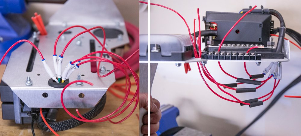
Re-Routing Wires from the Circuit Board Box

From the kit, this circuit board box has all wires coming out on one side. In order to minimize crossing over too much wire, I wanted to run wires from both directions. In order to do this, I had to cut open the side and top of the box. This allows for a cleaner run of wires to both the power and ground terminals on the battery.
Mount Box, Drill Holes in Bracket & Route Wires

Mount the circuit board box to the bracket and route the wires downward. I used a rubber grommet inside the pre-drilled hole so the aluminum wouldn’t year up the edges of the wire.
Mount Bus Bar and Terminal Block

Find the best placement for your bus bar and terminal block. The one thing you want to aware of is the proximity of the bus bar to where the bracket mounts to the firewall. The bus bar can get in the way of this bolt. We cover this later in the install process.
I drilled 4 holes for the terminal block but only used two because of the heads of the on the bolts were a little bit big.
Install Fuse Block, Cut 6 Switch Wires and Accessory (ACC) Wire

Mark and drill holes for your fuse block and then mount your fuse block in place. Then strip the switch power wires and accessory wire from the provided braided sleeve. Bundle 6 switch wires together and twist together but keep accessory wire separate. The ACC wire will need a separate add-a-fuse and to run into the fuse box.
Final Overland Equipped Bracket Layout

This is the final placement of all components on the tray.
Connect New Wire to Each Switch Wire

The provided switch has a pretty thin wire. I would say the provided wire is 16 AWG but more like 18 AWG based on their thin strands. Our 18 AWG stranded was much stronger. Hopefully, you can strengthen the wire with a stronger stranded wire.
Crimp Wires, Feed Heat Shrink and Prepare Terminal Rings
After crimping down each wire, feed a piece of heat shrink to each line.
Connect Ring Terminals and Fit Rings into Terminal Block

Connect waterproof ring terminals on each wire. The 14-16 AWG ring terminals were a bit too wide for the terminal block. We slightly pinched these rings down with a pair of needle-nose pliers. You don’t need rings, you can use forks as well.
Connect Ring Terminals to Terminal Block

The switch wires are labeled 1 – 6 which correlates to the switch panel. We wired each switch in order from 1 – 6 on the terminal block. When we need to add a light or new accessory, we can simply connect power to a switch and then ground that wire on the bus bar. The switch comes with 6 40A relays, 1 30A, and 5 20A fuses. Depending on the AMPs you are running through each switch, you can swap out fuses in order to support that accessory.
Power Wire from Circuit Box to Battery

Twisting the 6 switch power wires together – you can then crimp an 8 AWG connector to a 6-8 AWG wire. Finally, heat shrink the wires together using a heat gun.
Braided cable sleeve for Power Wire

After measuring and building your main power wire to the circuit box, you can finally add a braided cable sleeve. You don’t need to do this, I think it just makes for a cleaner look. The braided cable sleeve is really meant to contain multiple wires but it can give your set up a cleaner look and it can drain water effectively so it can be great for marine settings.
Ground Fuse Block to Bus Bar

Self-explanatory: Build a short 6-8 AWG ground wire from the Blue Sea Fuse block to the Blue Sea Bus Bar.
Extend Ground Wire from Circuit Box to Battery

Measure and build the main ground wire from the circuit box to the negative battery terminal.
Ground Wire from Bus Bar to Battery
Build a 6-8 AWG ground wire from the Blue Sea Bus Bar to the negative battery terminal.
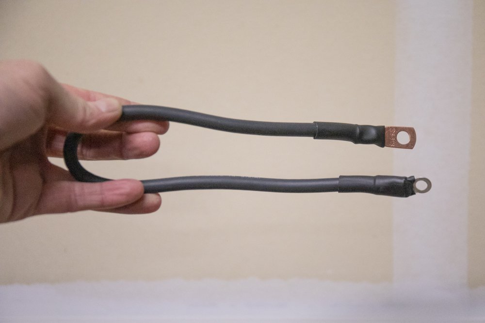
Connect Circuit Breaker from Fuse Block to Battery Power

Build a wire from the Blue Sea Fuse Block to a breaker and then to the positive battery terminal. You will need two separate wires pictured above. Although I bought the cheaper breaker to save $7 – I should have bought the actual Bussman Breaker linked above as this one broke. I can still toggle the breaker but the plastic button did break off.
Extend Accessory (ACC) Wire to Fuse Box

I had some soldering heat shrink so I wanted to test them out. The solder didn’t melt into the wire as well as I expected it to but it did work. With a hard pull from both ends of the wires – it held strong.
Testing Power on all Switches

I staged a real setup and tested everything once all the wires and harnesses were built. I used a factory Panasonic battery and ran every wire just as it would be in the engine bay. I tested each switch to make sure all 6 switches were firing on command. The switch provided to toggle on and off as expected. Onto the final install! I also tested this whole setup before building any harnesses a couple of days before (you may have seen this on an Instagram story).
Testing with Factory Halogen Bulb

If you are looking for something to test, use a factory bulb. If you have one laying around, it’s an easy hook-up. Get your polarity correct and test away.
Running Main Switch Wires & ACC Wire through Firewall

Best way to run wires through the firewall!
After years of running wires through the firewall, I figured out the best way to run big wires through the firewall.
I took an aluminum frosting tip from a cake decorating set and wrapped it around the switch connector clip. Then I wrapped it in some painters tape and finally drizzled lube all over the tip. Any lube or some vaseline should do. Forcefully working the tip through the firewall, I started to lube the entire area. Finally, I grabbed a pair of lineman pliers, gripped the head and shoved the tip through.
I have spent hours trying to push big clips through the firewall with coat hangers. This on the other and literally took 2 minutes with no cuts or scrapes/cuts on the hands/fingers.
Mount Bracket

Once the main wires are through the firewall – you can mount your bracket. You can see above the bus bar is trimmed.
Sand Edge of Bus Bar

If you need to trim your bus bar or anything else to get the bolts to fit into the bracket and firewall – now is the time.
Add-a-fuse for the ACC Wire

You’ve pulled two wires through the firewall. One was the main switch wires (6 in a braided sleeve) and the ACC wire. Now you need to add-a-circuit or add-a-fuse in order to power the switch on when you turn your ignition on.
Add a Fuse Location
You can run this add-a-fuse to many slots in the fuse block. Any circuit that turns on when the ignition is on will power your switch. The blank spot is trigged upon ignition, so is the ACC and many others.
Remove Center Console and Dash Cubby
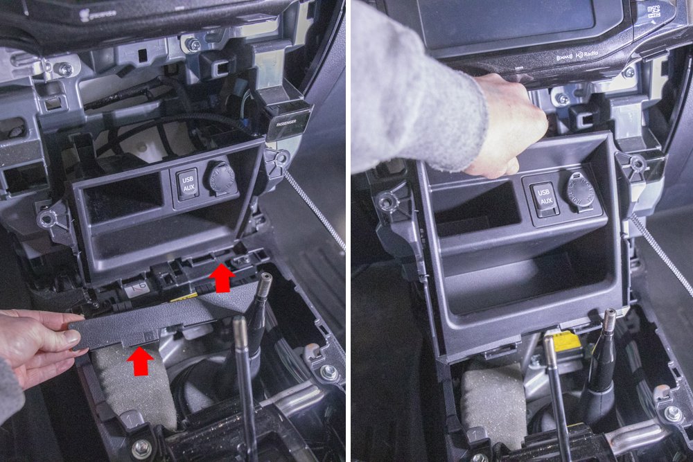
Let’s run the switch wire to the dash for our switch panel!
Start by removing your center console and center cubby. Here is a good overview of removing the center console dash. To remove the lower cubby, you simply remove one plastic piece in front of the cubby.
Drill Hole for Switch Wires in Cubby
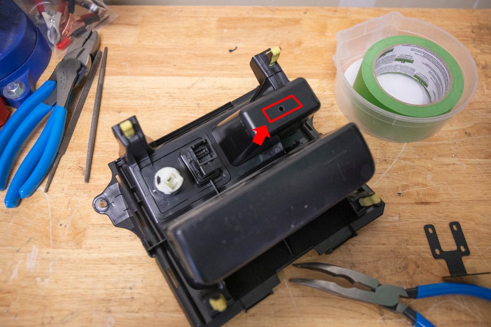
Drill a pilot hole and then determine how much space you need for the wiring harness clip. I drilled a few more holes until I caught an edge and then used a hot razor blade to cut a rectangle shape into the plastic (pictured in red). This gave me plenty of room to feed the wiring harness through.
Apply VHB Tape to Switch Bracket
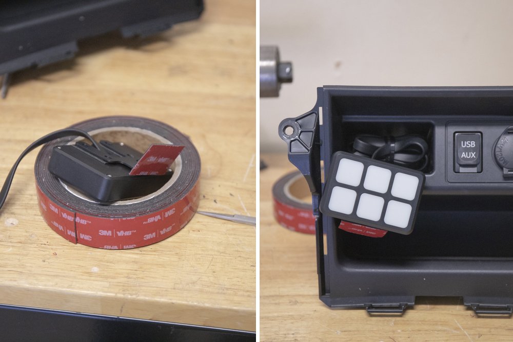
The kit comes with screws for the switch panel but I wanted to make sure I liked the spot before going all-in on drilling. I knew I wanted this spot, but before committing, I wanted to be sure.
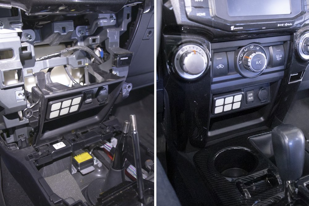
Position Switch Panel

After a week or so of driving around, I am not sure I need to drill anything, the VHB holds up well on both ends of the bracket. And it’s really simple to reposition to get exactly flush with the lower dash.
Final Test

Zip-Tie Wires from Firewall to Dash & Re-Install Center Dash
Connect All wires to Power and Ground
Final Thoughts?
For a fairly affordable switch, I think this turned out pretty nice – especially with the location of the switch panel in the cabin. It’s a clean setup.
The downside of the switch is that you can’t control it remotely via Bluetooth and it’s not “always-on”. But let’s be honest – how many of us are turning on our switches remotely? If having Bluetooth functionality is important to you then go with the switch pro. If you are looking for a simple off-road or marine switch that can get the job done simply on an ACC-on and then toggle on/off – then this is a good option.
This is one of those popular workaround mods where you don’t “really” need to spend $600 on a switch – this will accomplish the same main goal of turning on a light or accessory and organizing wires.
Switch-Pros and sPOD are going to have better customer service, a better warranty and likely backed by a community of support. You won’t get that with a switch from Amazon for $100.
But at the end of the day if it works and your lights come on – what else matters?
Is that switch panel still working after the two years?
Will this be the same process for the 8-gang switch panel by nirider? Thanks!
Why do you need the busbar and all the other stuff? The 6gang switch panel has relays included…
Nice clean install! Really like that you’re featuring a true DIY project here. Great job!
What amp should the terminal block be?
Is the Blue Sea fuse box always powered and the switch is only on when ignition is on? A use case would be a fridge, which should be able to receive power even when ignition is off.
If the Blue Sea is always powered, would you suggest a low-voltage disconnect in addition to the breaker? Would a low-voltage disconnect be better suited between the battery and breaker or between the breaker and fuse box?
Tyler, yes the Blue Sea fuse box is always hot.
Great idea on the low-voltage disconnect. Blue Sea sells one of these, you can see that low voltage disconnect here.
Install that in between your battery and breaker and then your breaker would run directly to the load (the fuse box) like it is above. You could almost replace your breaker with an LVD given the lack of room we have right here because you would also install an inline fuse in between the + battery terminal and the LVD. It’s a 65amp rated LVD but you can install the largest amperage fuse you plan on running through the Blue Sea Fuse block. If you have a fridge that pulls 14amps, then a 15amp inline fuse would be recommended.
Good idea man, thanks.
Hey Brenan nice job on the writeup! I just wanna let you know that I have a PowerTray for this switch panel. figured I’d chime in if you wanna offer your readers a more easy approach to this setup.
https://www.powertrays.com/products/universal-6-circuit-switch-panel-powertray-4runner-fj-cruiser-gx
Thanks! This makes it way easier.
Since your circuit control box already has fuses in it – why do you need the blue sea fuse box? Does not look like it is connected to anything? Maybe they came out with a new version of the panel – the one linked seems to be plug and play:
https://www.amazon.com/gp/product/B07QP5TQDK/ref=as_li_ss_tl?ie=UTF8
The blue sea fuse box is powered and grounded. This is for any secondary lights that I don’t need to control on a switch inside the cab. Think about underhood lights, or any other light or powered accessory where you have a switch somewhere else. Rear cargo area light, rooftop tent light, refrigerator, water pump, charging a secondary power station, the options are endless from random powered accessories for the 4Runner.
Maybe a dumb question but I was wondering why the circuit power wasn’t routed through the breaker like the fuse block? Could you run battery to breaker and then out to both circuit and fuse block (individual wires for circuit and fuse block but on the same terminal)? Or does the circuit with relays make the use of a breaker redundant?
Been following your guide and currently about mid build. Thanks for the inspiration!
There are fuses at each switch within the main circuit box. You can open the box and swap in a new fuse for any switch. With this setup, if any circuit were to be under too much or too little load and short, the fuse would blow. And, most switches (like the switch-pros and SPOD) recommend dedicated power and ground on the battery terminals. You can connect them at the same terminal but the Switch Pro instructions say that the power source “must be a direct battery connection”. So I went with the Switch Pro instructions inline with this build and gave the circuit a dedicated line.
Thanks for Patrick’s reply but I also wanted to know why you didn’t add a breaker like the main power line to the Blue Seas System box. With you own logic the Blue Seas fuse would blow if “any circuit were to be under too much or too little load and short, the fuse would blow”?
I have a Jeep JL and this mod somewhat applies to me as well aside from the bracket. Ive been looking for an alternative switch for my Jeep for a while now but the main options are so expensive – until now. Thanks for finding and wiring another solution. Seriously dude this site is something else. Not sure If I am welcome on these parts but just wanted to say thanks man. Your write-ups are pretty great over here. Thank you for sharing!
Great write up. I dont trust myself so I’m going to give to my installer to setup. In the process of piecing together the kit, I noticed it is a 8 circuit terminal block when it’s a 6 circuit fuse block? What is the amp for the terminal block, 20A?
Artie – the fuse block is separate from the terminal block so the amperage is different. The fuse block can run whatever amperage you want based on whatever fuse you slot into the block. The terminal block is connected to the switch which comes with 1 30A, and 5 20A fuses. Depending on the AMPs you are running through each switch, you can swap out fuses in order to support that accessory. So here, you can run your choice of amperage you want, just keep in mind the relays are rated at 40A each. You can also swap those out if you needed to.
I’m thinking about running this exact setup but cutting the cord to the switch panel and wiring it to some Toyota specific blue lit switches that match the others in the dash. Can you comment on the wiring going to the switch panel? Is it decent gauge wires? Do you think this would be easy to do? I assume its 6 wires, one per swatch with a common power for the switches and light.
I think that is a great idea wiring everything to AOB switches for example, but the 6 wires come into a single wiring harness that then connects to the switch. I don’t think it would be as easy as just reconnecting to individual switches. The wiring harness (6 wires) from the control box is met at a connector that merges those 6 wires into a single wire that feeds into the actual switch panel. I guess you can bypass the whole switch harness but then you are left with re-wiring 6 individual switches. Nothing is impossible. you just need a game plan. The product is so cheap, you can drop $100 on it – open everything up and start tinkering. Have fun and let us know if you come up with something. I would love to see a follow up on this and see if you can wire everything to 6 (or however many you want) AOB switches. That would be awesome.
I run this switch and it has been great for 15 months so far.
I installed this exact setup about a year ago. So far It’s still working fine.
One issue I had was I did not like the green or yellow lights, it didn’t match the rest of the dash lights. There is a way to change the colors of the lights on the switch, but hold onto your shorts because it requires busting out the LED’s so one of the colors doesn’t wash out the other color. It works but it’s not perfect.
Second issue I have is trying to get those dang little labels squared and straight on the Chiclet tile switches. It’s a major pita and I still don’t like the way they look even after multiple sessions trying to get them straight and flat.
Can you upload a photo of the revised color of the LED output now?
I purchased mine already wired and ready to go from s-tech http://www.stechswitch.com
Here’s a link to the video on changing the colors https://youtu.be/Fho7IY_TzBI
Just for clarification – you went with the S-tech system instead of layout done here? Was it a complete setup without any additional items? Thanks.
Yes, the S-tech system is complete. Just mount the switch in the cab, control box under the hood and connect the various wiring and you are good to go. It does not require all of the other things (extra terminals, fuse blocks, etc) that Brenan added to the install pictured. His solution is awesome, but not necessary. You will need to choose some sort of mounting solution both in the cab and engine bay.
Nice, thanks. Super easy – thank you for sharing.
I have been looking for an affordable way to wire up a switch the cabin and this is great. It would be nice to see a few accessories loaded to this switch, specifically some big light bars (you mentioned a Pro6 on Instagram) or something with high AMPs to ensure this circuit board can control the constant load being demanded. If this control box works out for the long term, this would be a game changer.
May be my lack of knowledge but what is the additional fuse box for?
No worries – the fuse block is to run anything without a switch. The switch circuit provides 6 switches (buttons) inside the cab. Most forward, side and rear-facing light bars will be on this circuit with control from the cabin. For other accessories that are turned on/off elsewhere, you can run these to the fuse block (power and ground) with the preferred amperage. For example, you may have an on-board air compressor, additional under-hood lights, an on-demand road shower, or anything else that has a switch somewhere else. This set-up offers a solution for just about all powered accessories on your build… switches inside the cabin or anywhere else.
Yes! This is such a great write up.
I was halfway to this build already with parts that I had, including the Overland Equipped plate and the Blue Sea components.
I started a build similar to this but started doubting the setup. You put together the missing piece…rad!
Drew, awesome! I am glad it helped!