
Article Written and Submitted By: @Savs4Runner
Grille Marker Lights & Raptor Lights – Step by Step DIY Installation on 5th Gen 4Runner
This is a fun project. It adds extra visual appeal and it makes the 4Runner look cooler, especially at night time. Imagine seeing a 4Runner in your rearview mirror with these marker lights. You want to be that guy behind the wheel. It is a simple minor mod and I am going to be as specific as I can be. I already had this installed so I am going to do my best to explain with pictures as well. My advice is to take your time and enjoy the time working on this.
First, make sure you have everything set and ready to go. I purchased most of these off Amazon. If they are not off Amazon, you can find them at any auto parts store. I also went to True Value and Auto Zone. But, you can get 90% of this if not everything on Amazon, so it should make the purchasing part go smoothly as we have all the links right here.
Keep in mind, this install offers multiple options for installing and running the 4Runner marker lights. You can install the lights as an on/off switch or install the lights to run ignition on. Try not to get overwhelmed by all the pictures and products. Just read through this install before you decide which direction to go.
Non-DIY Raptor Light Option:
If you want to skip the DIY raptor light mod and just buy one pre-built, there are hundreds of options out there now. From hand-built makers in the states to ones overseas, there are plenty of options to choose from.
- CarTrimHome.com: Check Price
- Universal (multiple options) 5th Gen Raptor Light Kit: Check Price
Materials for Marker Lights
- Marker lights
- Wires
- 1 25ft 14 gauge RED wire
- 1 25ft 14 gauge Black wire
- 22 gauge RED wire (True Value)
- 22 gauge WHITE wire (True Value)
- (Optional) 14 gauge 2-pin Quick Disconnect harness
- Wire covers
- Heat shrinks
- Ring crimps
- Butt splice connectors
- Zip-ties
- Power supply
- Option 1 (Ignition On): Add-a-circuit adapter
- Option 2 (On/Off Switch): Relay with a switch – See second section below
Tools for the 4Runner Marker Light Install Mod
- Wire cutter
- Heat gun
- Black electric tape
- Scissor
- Safety glasses
- (Optional) Dremel
- (Optional) VHT Nite-Shades spray can
- (Optional) Solder gun
Marker Light Installation Options

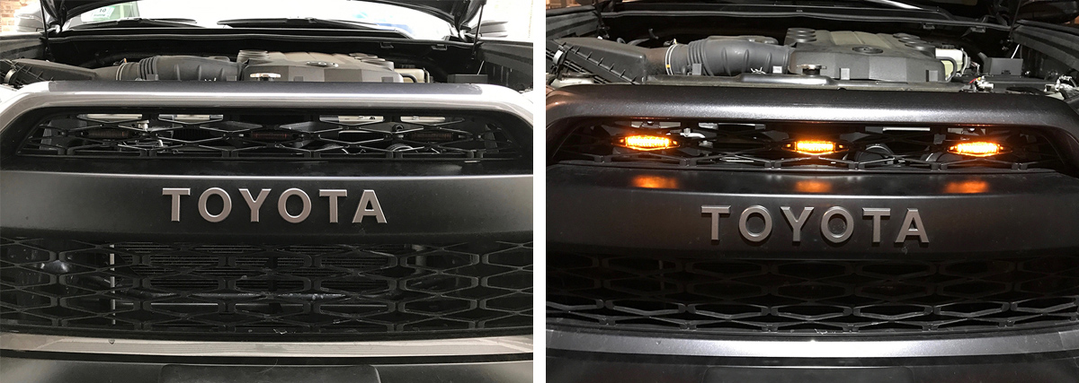
- Trim the edges: Originally, we put the lights on the front of the grill although there are options. Some of us like it better if it is shown from behind the grill. If you want it to be shown behind the grill, you would have to trim the edges of the lens. I used a Dremel to trim the lights. Use safety glasses and take your time cutting the edges for the best result. I did this method right away.
- Tint the lens: Rarely, we customize the lens but I’d rather have more of a stealth look in the grill than see the orange lens during the day. I went ahead and used 3 coats of VHT Nite-Shades on the lens of the lights. The lights are still bright enough, while the lens blends in the grill when the lights are off. I did this method a few months later.
- Add a Quick Disconnect: For my own good, I added the quick connect harness in between the 14 gauge wires. The quick connect is a plugin harness where you can unplug and plugin. I wanted to have this so I can remove the lights if necessary. Who knows, there could be a time where I can take them out and then I can put them back in easily. It’s better than taking all the wires apart. I even took them off so I can take some pictures and add them to this write-up!
- Soldering wires: Soldering wires would be a better option than using butt splices connectors. It is more secure and permanent. I would have used the solder gun but I didn’t have one and I do not have any experience with it. If I were to do this all over again, I would buy the solder gun and start practicing with it before I feel comfortable.
Marker Light Install Mod – Quick Notes:
- Marker Lights: The light comes with 2 wires- red and white. The red wire is positive while the white wire is the negative. I will have the white wires connect to the black wire.
- Extra wires: I got extra red and white wires for an extension since the light came with short wires. I will have all 3 lights merge together on the right side of the engine (driver’s side) so extending these wires will help bring them over to one spot.
- Connecting wires: When I connect all the wires together, I use the butt splices and then I would cover them with the heat shrink. Make sure you have the heat shrink tube in one of the wire before connecting the butt splices. I use the heat gun for shrinking the tube over them.
- Covering wires: I decided to cover most of the wires with the flex/split loom tubing. I used the flex loom to cover the wires from the lights so you won’t see the red and white through the grill. I use both the flex loom and split loom to cover most of the wires just to have a little extra safety from abrasion in the engine bay.
- Two different setups: I personally like to be able to control the marker lights by having them turned on or off anytime I want. I already have the Shrockworks Bussmann RTMR module and the Air on Board switches installed. The Bussmann RTMR has 5 relays, some are going to be used for my light bars (will be installed soon) and future accessories as well. I had the lights connected to one of the unused relays in the Bussmann RTMR. I will also show an easier way if you are not interested in the “On/Off switch” setup. Don’t worry, the “Ignition on” setup is the popular option.
4Runner Marker Light Install Mod Step by Step (PHASE 1):

I connected both red and white 22 gauge wires into the marker lights wires. Red to red. White to white. I did this on all 3 lights. Make sure each light has enough length across the inner grill into the opening slot on the right side (Driver’s side).
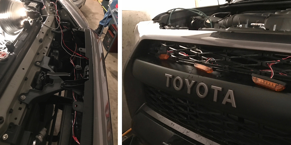
I removed the radiator cover in order to have access into the area behind the grill. I did the measurements with wires in the engine in order to get the right length.
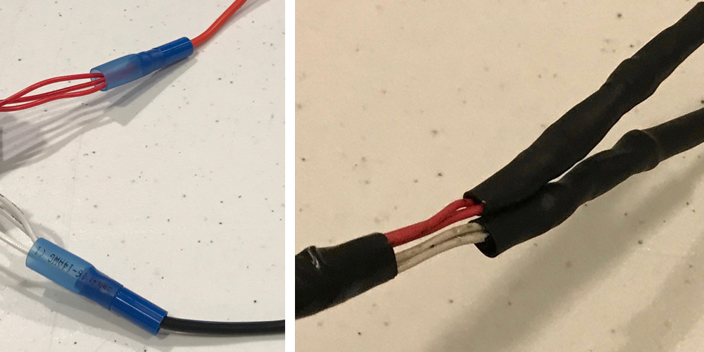
I connected 3 red wires into 1 14 gauge red wire. All 3 red wires were 22 gauge each so I was able to fit all 3 in one side of the butt splice. I did the same thing with 3 white wires into 1 14 gauge black wire.

I cut the middle of both black and red 14gauge wires so I can install the quick connect harness that way I can remove the lights if necessary. Wiring is completed.

I zip-tied the lights behind the grill. Then I secured the wires with zip-ties, having them run across the inner grill located below the lights.

I had both black and red wire run along the driver’s side fender. I used more zip ties for securing them.
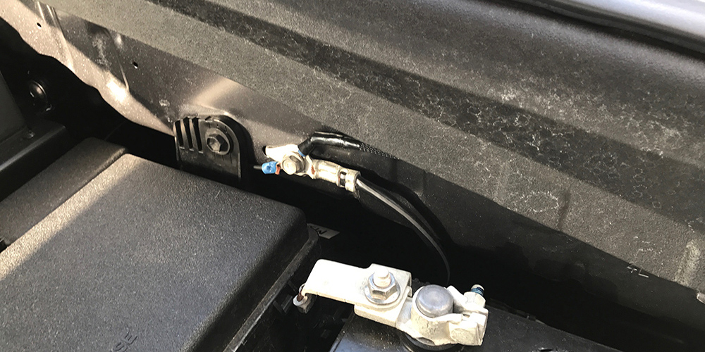
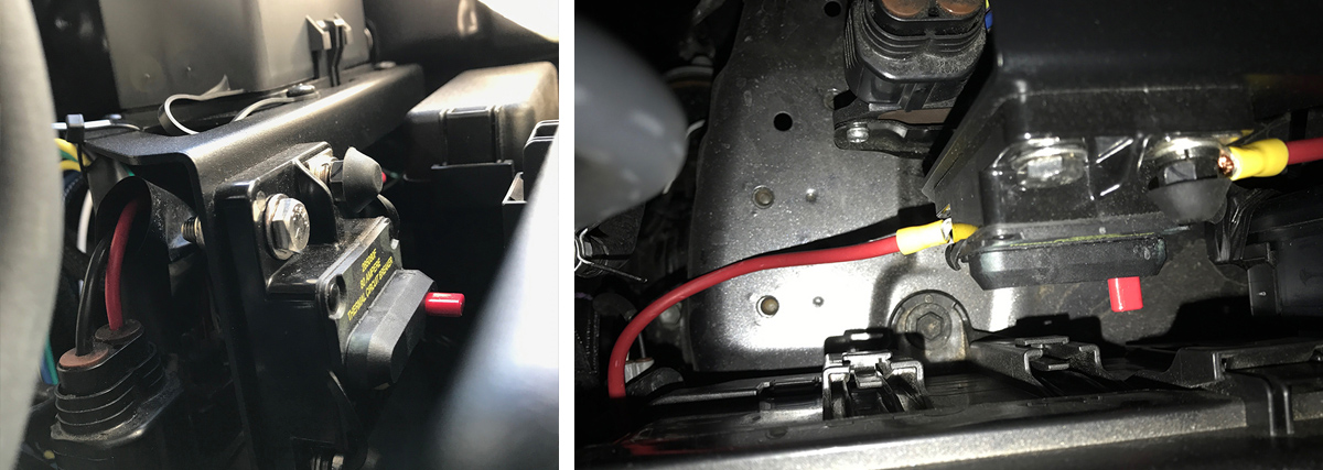
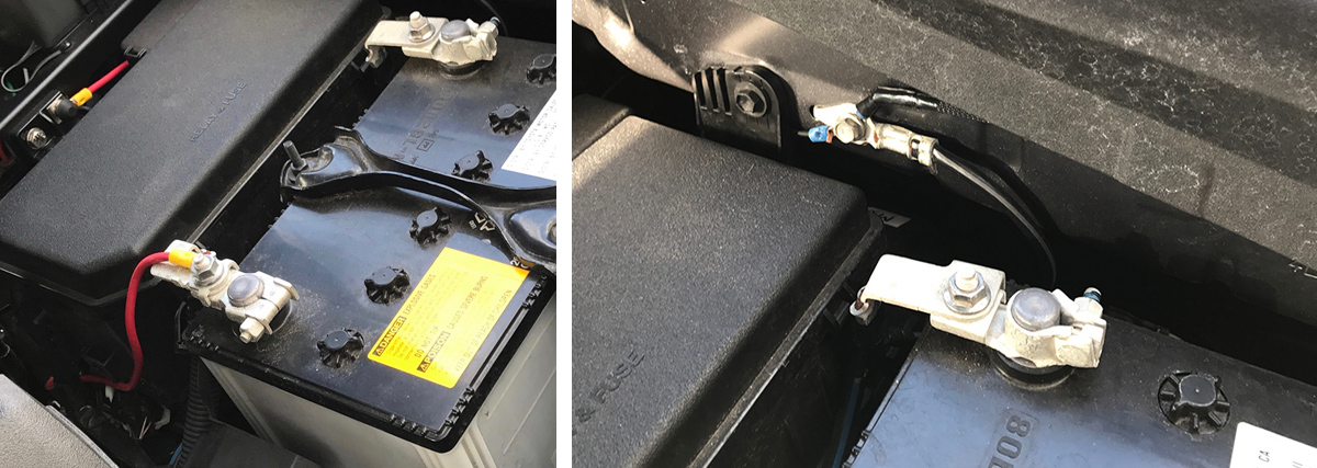
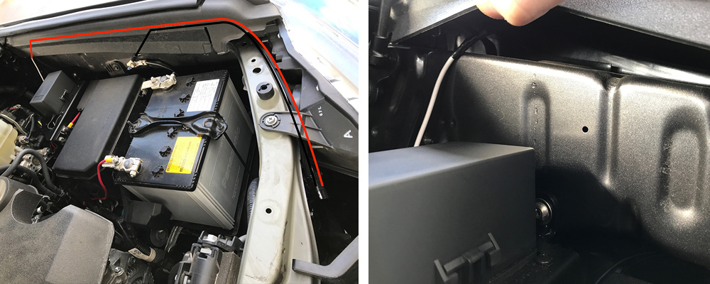
The black wire would go straight to the existing chassis ground that is located next to the battery. I use a 14 gauge ring crimp to attach the nut to ground.
Different Marker Light Setup Options
Option #1: The “Ignition on” setup (easy)
For this setup, all you have to do is run the red wire through the firewall for access to the power source. The lights will go on every time you turn on the key.
- You Need: Add-a-circuit adapter
Step by Step (continued):

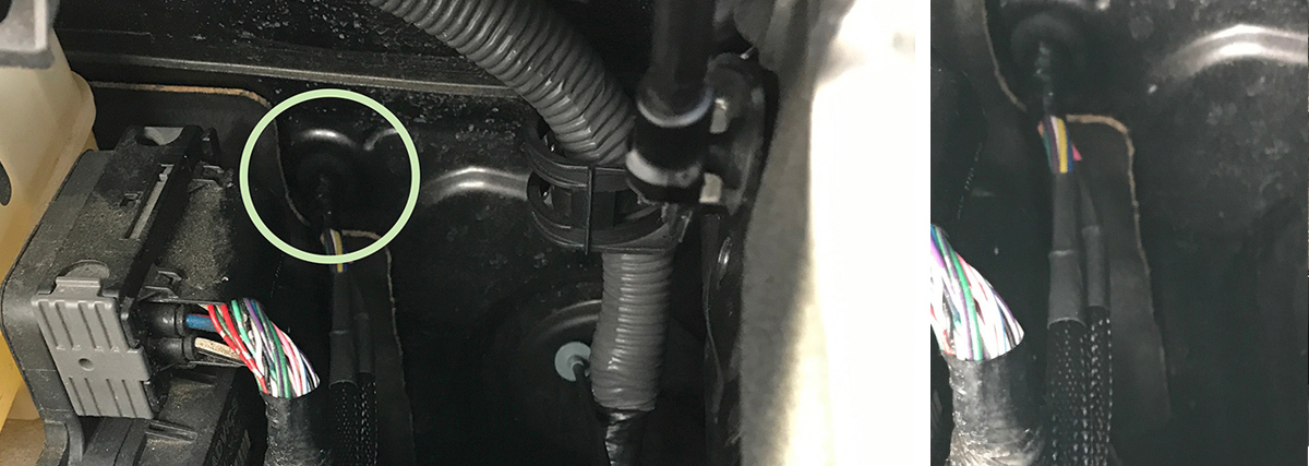
You will see a circle rubber plug in the engine right in front of the Driver’s dashboard. This allows you to pass the wire into the interior of the vehicle. You can remove it and create a little hole for the wire to go through it. I used a drill bit. Re-install the rubber plug back in place when done.
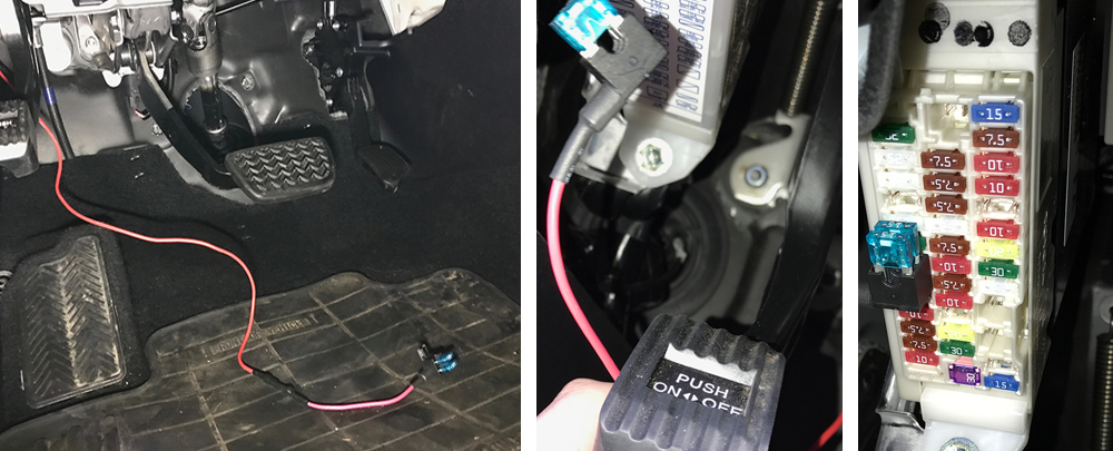
Once the wire is pushed in from the engine side, go under the driver’s dashboard and carefully pull the wire towards you. Connect the add-a-circuit adaptor on the end of the wire and plug it in any of the empty slots on the fuse panel located on the left side of the parking brake.
Turn on the key and they’re ready to go!
Option #2: The “On/Off switch” setup (Advanced)
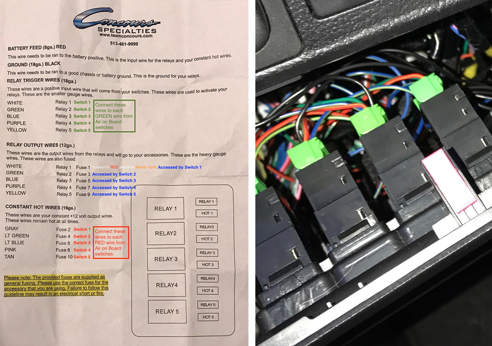
If you have this setup with Shrockworks pre-wired Bussmann RTMR and Air on Board Switch, then you are all set! Just connect the red wire to one of the output wire from the Bussmann RTMR.
If you don’t have this setup and are interested. Here is what you have to do.
You will need to purchase the Bussmann RTMR and the Air on Board switch. There are other kinds of relays out there but I find this one to be perfect.
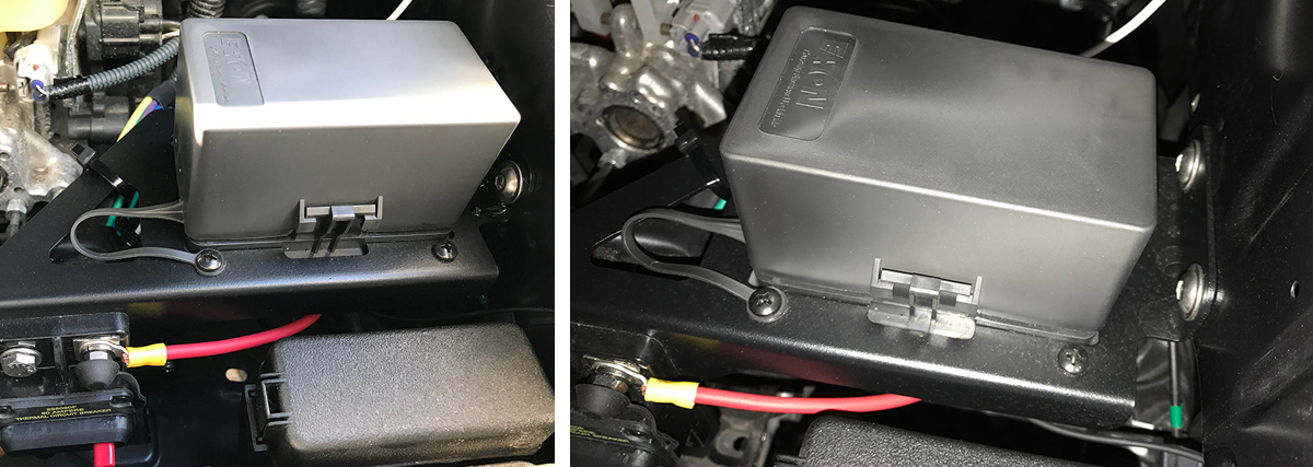
The Power Distribution Module with pre-wired Bussmann RTMR is very simple as Shrockworks will have it pre-wired and ready to go. It includes 5 fused relays and 5 constant draw circuits. With the 5 relays, you can add 5 different accessories!
The module bracket mount is designed to fit in the 4runner so it is the most trusted bracket yet to have it installed for the Bussmann RTMR. The installation instructions come with it, along with screws that are made to fit in the unused holes on the driver’s side fender. No drilling required.
This would be the best choice for 2 main reasons.
- You are planning on more installs in the future like adding light bars and other accessories. I have this setup because I am using 3 out of 5 relays. The 1st relay is being used for the marker lights and the 2nd, 3rd relays are for my Rigid light bars. I now have 2 relays remaining for future accessories.
- You are enjoying a project that includes wiring, but you wouldn’t want to start from scratch with all kinds of items required to create a relay. If you want to make one, take a look at this website. Good luck.
Item List
- Relays
- Fuses
- Switches
- Ring crimps
- BusBars
- (Optional) 100A, 5 Screw Common Busbar
Optional Use for BusBars
BusBars: The BusBar takes care of all your accessories’ grounds in a more organized way. The Blue Sea Systems common BusBars seemed to be the popular choice, and I would get this one if I was interested. I do not have this since I am okay for now by having my grounds overlapping on the existing chassis ground.
Option #2: The “On/Off switch” – Getting Started:
Bussmann RTMR: The pre-wired Bussmann RTMR Module have a positive and negative wire for all relays. This leads to only 3 wires coming out from each relay.
- Output wire: This would connect to the accessory.
- Trigger wire: This would go through the firewall to connect to the Air on Board’s trigger wire.
- Power wire: This would go through the firewall to connect to the Air on Board’s power wire.
I already had the 10 wires (5 trigger wires, 5 power wires) through the firewall and connected to my 5 air onboard switches ready to go while waiting for new accessories to be added.
- Fuses: Fuse/diode are required and there are options as they tend to be a personal preference. I like the idea of circuit breakers so I went with this method. The module bracket mount has a spot specifically made for the Blue Sea Systems 80A circuit breaker.
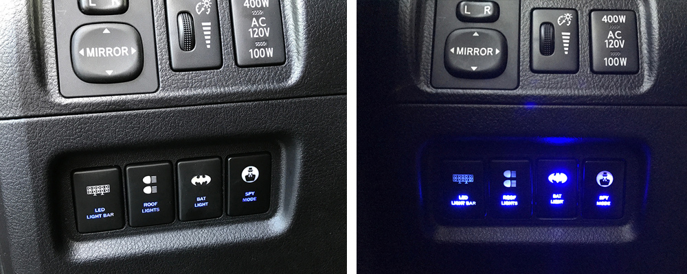
- Air on Board switches: 5th generation 4runners comes with 5 blank buttons and I filled them with 5 Air on Board switches so they are ready to go. The switch comes with 4 wires.
Option #2: The “On/Off switch” – Step by Step:
- Trigger wire (green): This trigger wire would connect to the Bussmann’s trigger wire.
- Power wire (red): This power wire would connect to the Bussmann’s power wire.
- Ground wire (black): This ground wire would connect to the existing chassis ground located right behind the dashboard on the left side of the steering wheel.
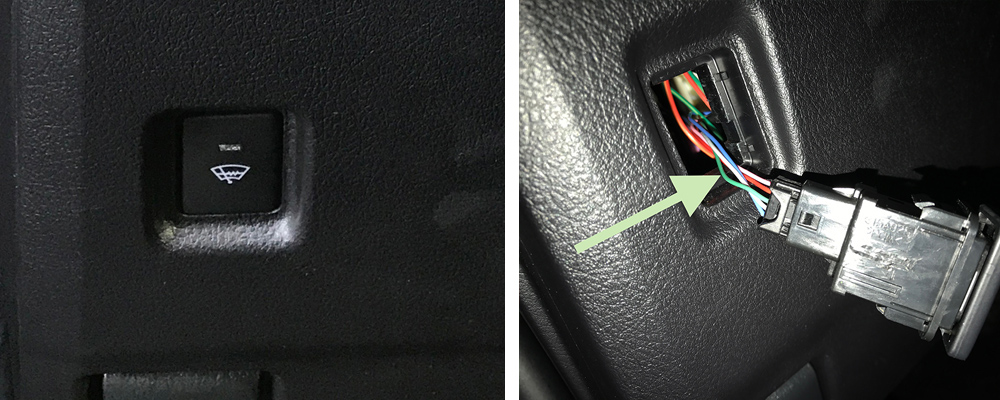
- Dash light wire (blue): This dash wire would connect to the existing wire from the wiper warmer switch.
You can either get 1 switch for now or get 5 switches and have them all connected and ready to go. Already installed: Again, I already had this installed so I am going to do my best to explain.
Marker Lights Install (Finish)
Before installing in the engine bay, attach the circuit breaker on the module bracket mount. Cut the positive wire (from the Bussmann RTMR) and install ring crimps so they can be attached to one end of the circuit breaker.
Follow the instructions and carefully install the module bracket mount in the engine bay.
Install ring crimps on the positive wire and the negative wire. Red wire to the battery and the ground to the existing chassis.
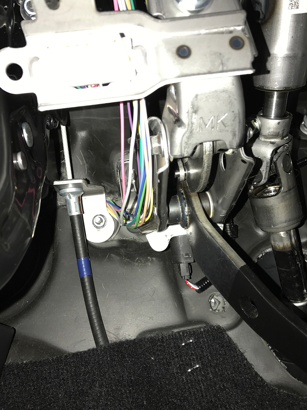
You will see a circle rubber plug in the engine right in front of the Driver’s dashboard. This allows you to pass the wires into the interior of the vehicle. You can remove it and create a hole for the 10 wires to go through it. I used a drill bit. Re-install the rubber plug back in place when done.
Once the wires are pushed in from the engine side, go under the driver’s dashboard and carefully pull the wires towards you and bring them up behind the dashboard area on the left side of the steering wheel.
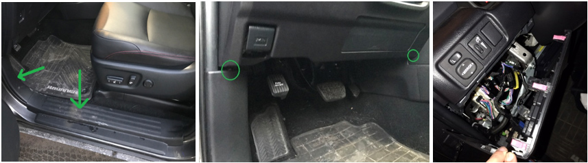
You will have to take out the upper dash for access to install the switches and connecting wires. First, pop-out the bottom door pieces (green arrows). Then unscrew the bolts (green circles) that way the dash can be pulled out farther. Lastly, gently pop-out the dash
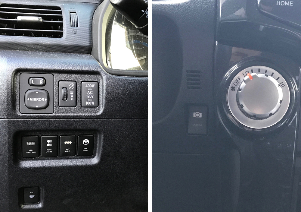
I pushed out all the blank buttons and replaced with the 5 Air on Board switches. I also moved the 2 factory buttons so I can have the custom buttons together in the same row. The 400W button moved up while the wiper warmer switch moved down.
Then I connected all the wires together. If you only got one switch, just connect the 2 wires from the first relay to the one switch you have. Look at the chart. You could store the rest of the wires safely behind the dashboard.
The other 2 wires (black and blue) would stay behind the dashboard. I had all my 5 black wires connected together and used a ring crimp to ground to the existing chassis that is located right behind the dashboard on the left side of the steering wheel.

I also had all my 5 blue wires connected together and tapped it in the green wire that is connected to the wiper warmer switch. All you have to do is cut the green wire from the wiper warmer switch and tap the blue wire in between, then reconnect it.
The switch description lights would be on when your headlights are on. The lights on the logo would be on when you press the button. Just make sure they are working and then you can close up the dashboard.
The red wire will connect to one of the output wire from the Bussmann RTMR.
Play with the button and they’re ready to go whenever you want to!

I have a 2020 limited, can you splice into the existing running lite wire without going to the fusebox?
I decided to go with an AVS Aeroskin Lightshield and vampire tapped right into the fog lights
Can you explain this more? That’s what I am
trying to do too
Excellent article,
what would be the procedure to add these grille lights to the DLR switch? Is it possible? If yes, the fuse needs to be changed?
thanks!!
So I’ve done some reading per the link you provided above regarding the diy bussman, and that would be an awesome thing to put together – eventually. But I was curious, what are the key differences between the switch pro 9100 and the bussman rtmr? Don’t they both provide fuse boxes and terminals? There seems to be a huge price difference.
Hey Brenan, have a quick question regarding this setup, great walkthrough by the way. What’s the purpose of the 22 gauge red and white wire? Would it be possible to go with a 20 gauge or 18 gauge?
Also, are they outdoor specific or only meant for indoor?
This whole wiring, electric concept is still new to me, any resources to get up to speed would be also greatly appreciated.
-Yousif
Yousif, This was actually a post from another user and before we had unique author bios set up. Standby on this.
Couldn’t you just tap into your existing running light power sources(Positive wire) under the hood and splice in a add a circuit fused line?
I was thinking the same thing Dan, did you ever try it?
Russ, go back to the AironBoard website and search under ‘light blue’ for the color – they have a blue that matches the OEM blue lighting on their website.
Im working on a 2018 4Runner using the “ignition on” method. When plugging in the “add a circuit” adapter to my fuse panel I picked an empty slot closest to the firewall. This slot must be an “always on” spot because my marker lights were on with the ignition turned off and lights turned off. When I moved the circuit to an empty slot closer to the drivers seat I didn’t have this problem. Marker lights turn on and off with the ignition.
Hey, I was looking on AOB(Air on Board) and they don’t have the blue switches for the 2010+ 4Runners. Where did you find the blue lights on their website?
Thanks!
Russ,
There are tons of switches and panel option on Amazon. And, all over the web. For general switches, check these out. FOr the AOB(Air on Board) website there are blue switches, you just have to drill into the Toyota category and browse through a few pages.
Nice. Is there a video available?
John,
No video available for this install at the moment. We were considering doing this mod and shooting a video for it. We’ll see what happens.