
KC HiLiTES Cyclone Rock Lights as Courtesy Lights on the 5th Gen 4Runner – Similar to the Toyota LED Illumination Package
This mod may work on many other Toyota platforms, Tacoma, Tundra, Landcruiser, Sequoia, etc. Call it the DIY LED Illumination Package, Rock Lights as Courtesy Lights, or whatever you want. Either way, this is a pretty awesome mod.
Courtesy lights, otherwise known as puddle lights, they serve many purposes. Typically located on the side view mirrors, or near the foot wells of the vehicle, provide you with visibility the ground below.
These exterior lights conveniently illuminate whenever unlocking or opening a door of the vehicle assisting you from either side-stepping puddles at night, or even in lighting up the area to help you find an item that may have dropped out of the vehicle.
The Goal
The goal of this project is to trigger the rock lights to function as an everyday courtesy light if needed. This project is based on Toyota’s aftermarket LED Illumination Package.
However, instead of using the lights that they offer, I chose to sub them out for higher quality, more durable set of rock lights, the KC HiLiTES Cyclone kit for the Jeep JK.
PLEASE READ FIRST: This article piggybacks off of Brenan’s previous installation of the KC HiLiTES Cyclone rock light kit. A lot of references are made to this article, if you haven’t already read it, check it out. There are two separate pages on the install. You can find a brief overview here and the full step by step installation here.
KC Rock Lights as Courtesy Lights

Parts Used:
- The Cyclone Light Kit: Check Price
- The RGB Kit: Check Price
- OTRATTW V-Series SPDT Switch: Check Price
- OTRATTW V-Series Rocker: Check Price
- Rago Fabrication Rock Light Mounts: Check Price
Tools/Time Required:
- Installation Time: ~7 Hours
- Basic shop tools
- Wrenches & sockets
- Open-end wrenches
- Philips screwdriver
- Stubby screwdriver
- Allen keys
- Wire strippers/crimpers
- Wire cutters
- Heat shrink gun/lighter
- Waterproof butt splice connectors
- Waterproof fork/ring terminal connectors
- Heat shrink
- Wire Loom
- Electrical tape
- Zip Ties
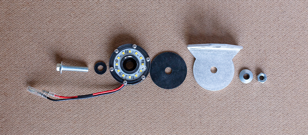
- 8mm Flange Bolts*
- Neoprene Washers*
NOTE: *Hardware optional depending on the lights used in your application. The reason why I changed over to new hardware with neoprene washers was to isolate the light from becoming grounded to the frame by direct contact.
Map Out Wiring Harness and Switch
The Toyota 4Runner’s dome light is connected +12v at all times, and triggered by a ground (-). Our rock lights will be connected the same way, and triggered by the dome’s ground, as well as 2nd ground for independent control.

Step #1a: Route Driver Wiring Harness to Passenger Side
– Run the harness along the inside of the engine bay, following the frame rail
– Remove Terminal Ends from wiring harness
– Elongate the harness
Step #1b: Run the Passenger Harness to the Driver Side
– Run the harness along the inside of the engine bay, following the driver side frame rail
– Remove Terminal Ends from wiring harness in the engine bay
– Elongate harness

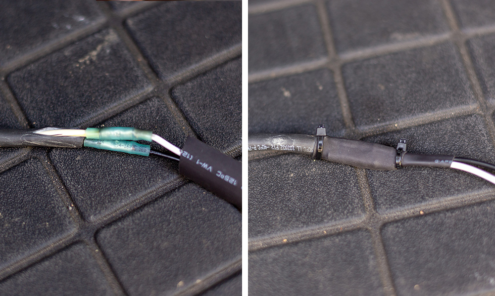
(Underneath the electrical tape is a waterproof connector and heat shrink)
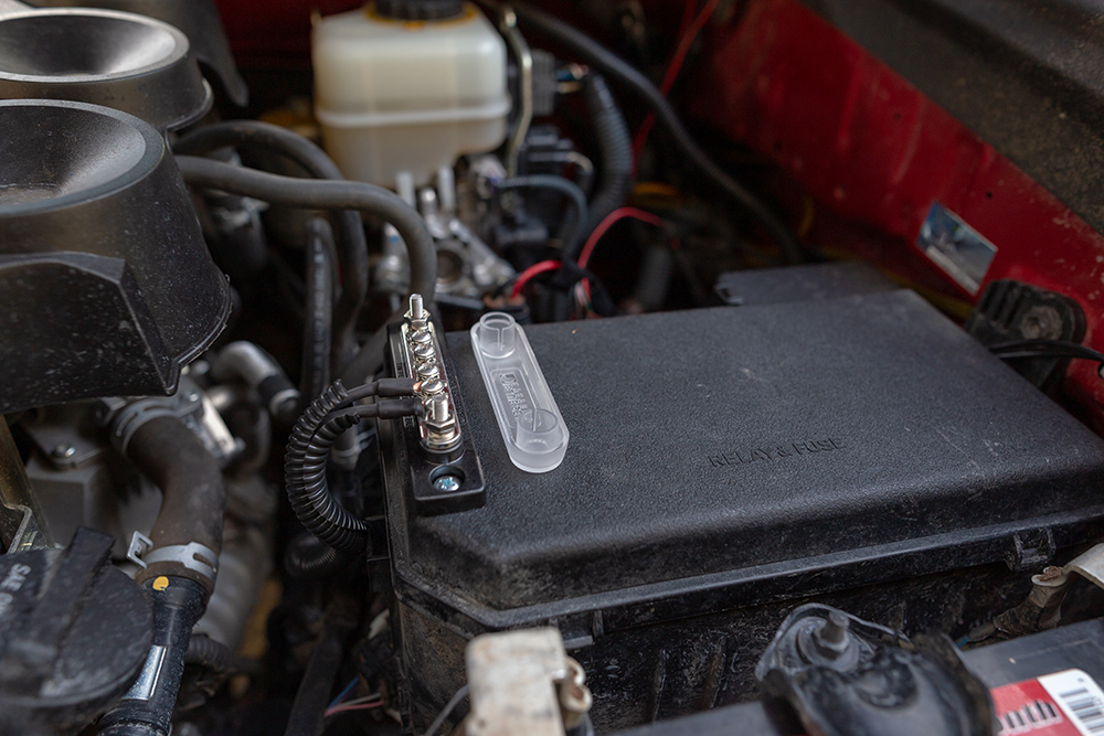
Step #2: Connect Passenger/Driver Harness to Busbar
Attach busbar to fuse box lid
– Add forked terminal ends and heat shrink to white wires from harness
– Connect the white wires from both harnesses to the busbar
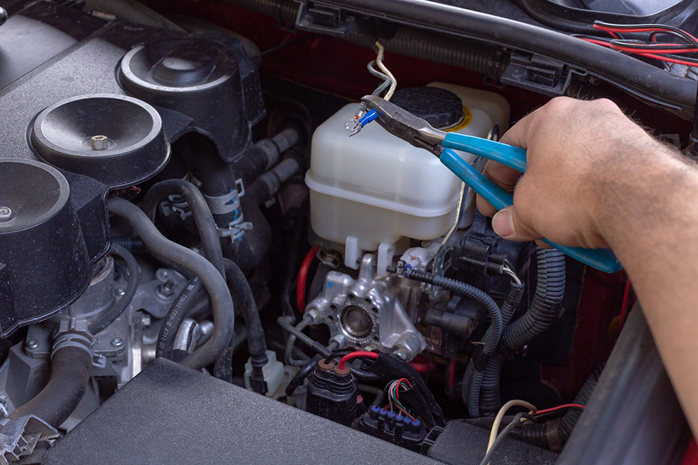
Step #3: Cut Open White/Green Wire Sleeve
In this installation, we will be running
-Discard provided KC Switch
-Discard brown ground wire from the provided switch
-Cut open white/green wire sleeve
– Shorten white wire to retain the fuse in the middle
– Attach one end of the fused white wire to the busbar and the other end to the battery.
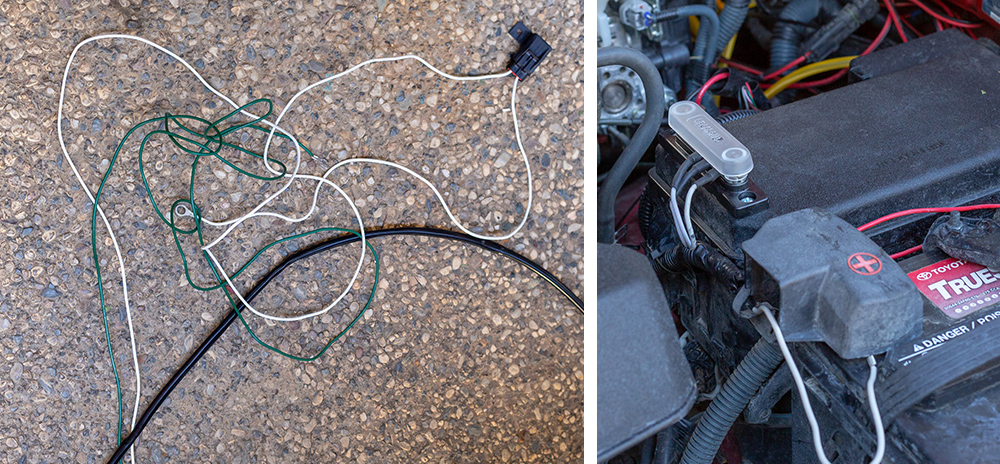
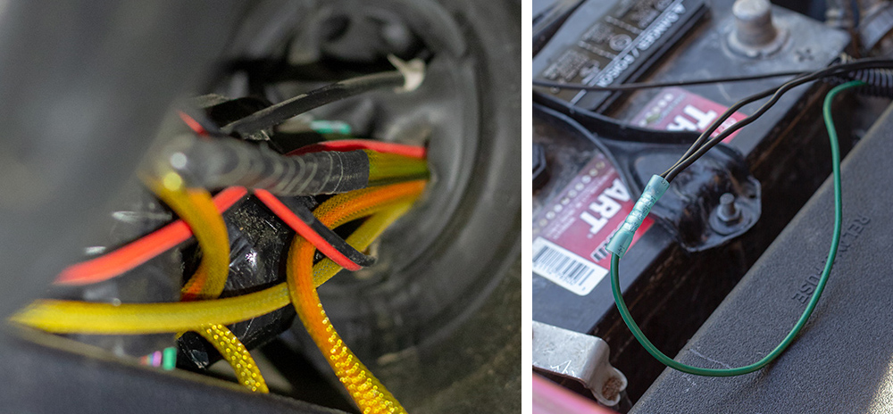
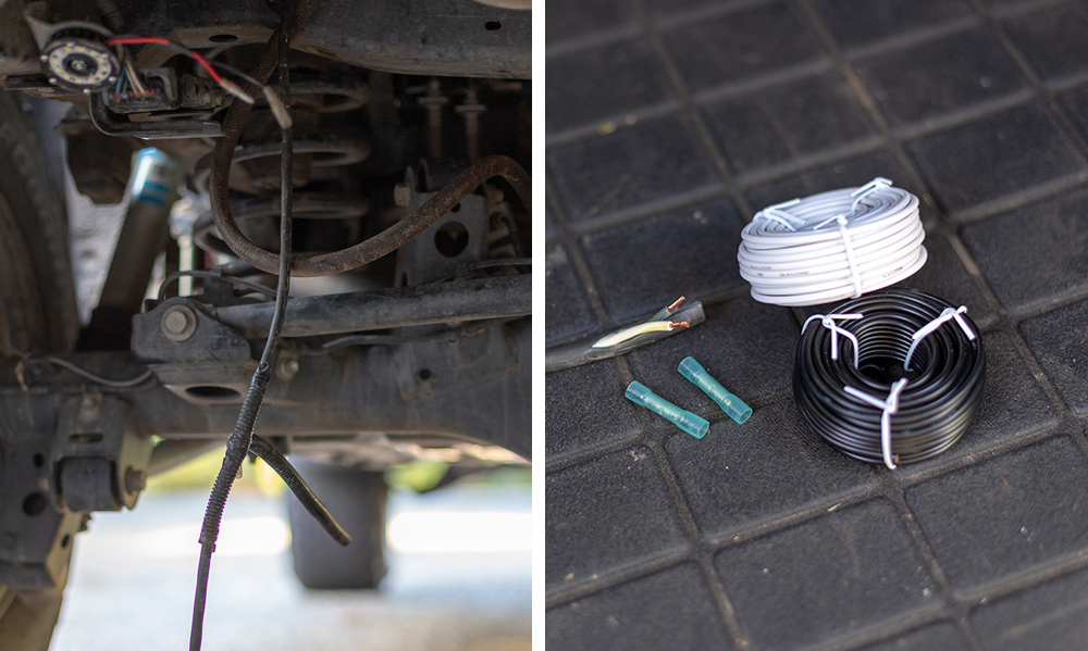
Step #4: Running the Switch Wires
– Run provided green wire with a new black wire into cab of the vehicle
– Connect the black wires from both harness into one end of a butt splice, attach the other end to the green wire in the engine bay
– At a circular connector and heat shrink to the engine bay portion of the new black wire
– Connect the black wire coming from the cab to the ground location in the engine bay of the vehicle.
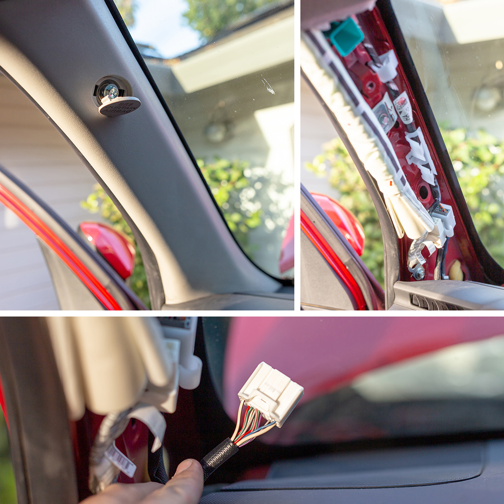
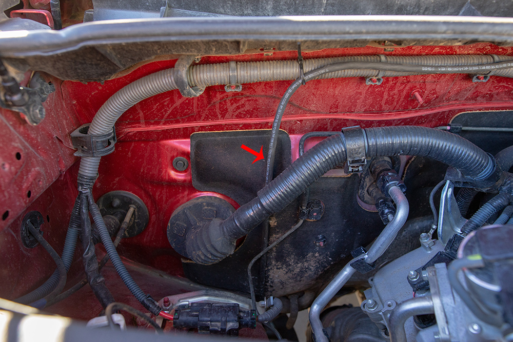
Step #5: Wiring the Trigger
– Remove Driver’s side A-pillar cover with 10mm socket
– Using a Red T-Tap, connect a new green wire to the green wire in Pin 15 of the FS1 Connector in the A-pillar.
Step #6: Wiring the Switch
Remove the top left dash piece containing the OEM button blanks by firmly gripping and pulling straight towards you

Run the new green wire down and feed through into the top bank of switches located to the left of the steering wheel.
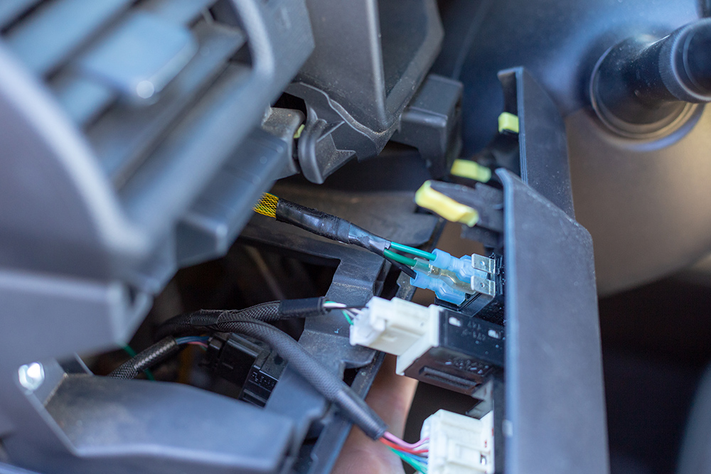
This new green wire coming from the A-pillar will attach to top position (outgoing) of the SPDT switch.
The primary green wire from the engine bay will attach to the middle position (incoming) of the switch.
Attach the black female female terminal connector from the engine bay to the bottom position (outgoing) connector of the SPDT switch.
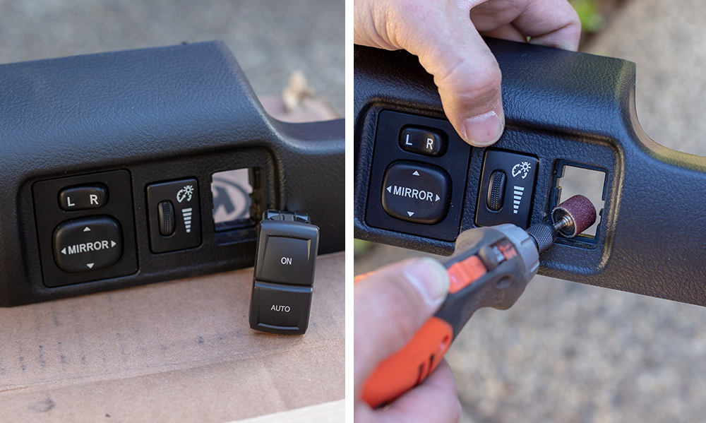
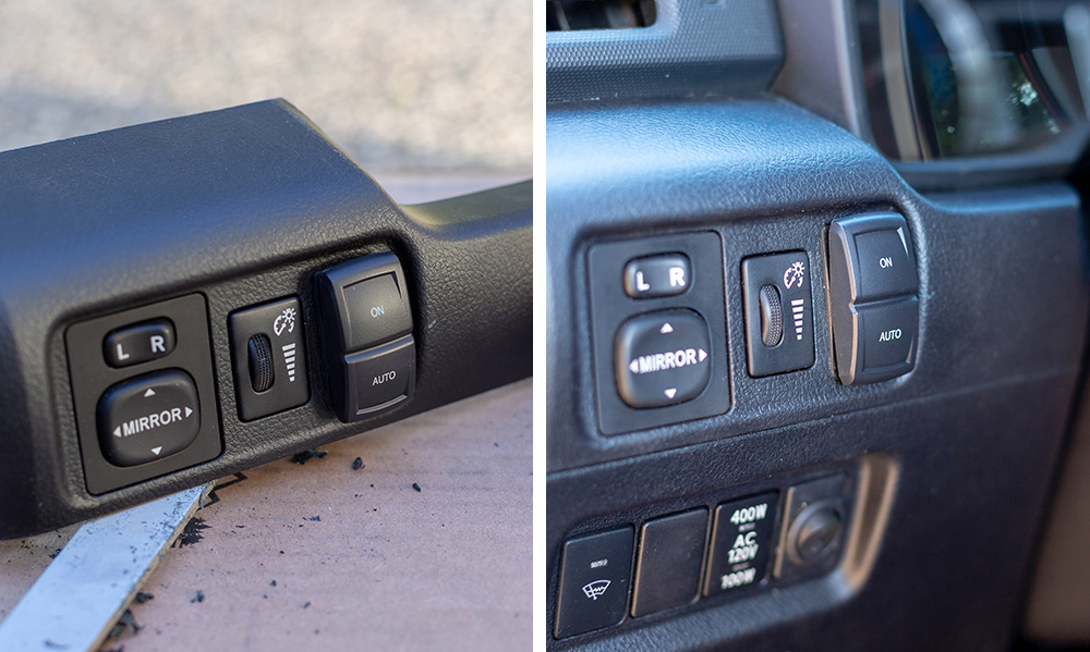
Step #7: Fitting the Switch
Modify the switch hole to fit the new SPDT switch from OTRATTW.
The new switch is just slightly larger, and will need some Dremel work to ensure correct fitment.
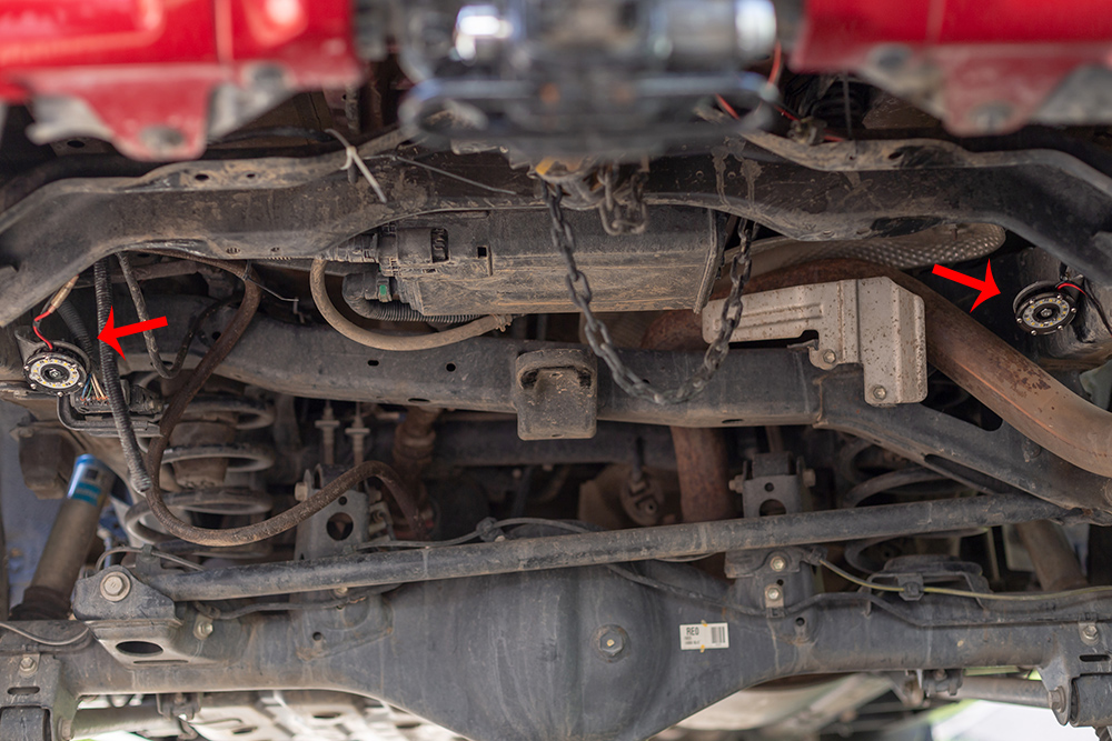
Step #8: Mounting the lights
I opted to upgrade to the Rago Fabrication rock light mount for the KC Lights. I preferred having the multiple mounting points, and larger flat surface for the light to attach to.
For this install, I followed the suggested installation points to match the Jeep JK as provided by KC Hilites. I chose to follow their layout for the purpose of having more rearward light as opposed to the locations of Brenan’s Rock Light Article. In the end, placement of the lights is a suggestion, as the final location may change based on your preference and needs.
Step #9: Driver Rock Slider Bracket
Continue the run of the harness from inside the inside of the engine bay down alongside the frame rail and rock slider.
Step #10: Driver Middle Slider Bracket
Continue the run of the harness along the driver side of the vehicle, finding a proper placement for the middle driver side light.
Step #11: Running Wires from Driver to Passenger Side
Repeat driver side harness steps for the passenger side
Extending the 3rd Wiring Harness For the Rear of the Vehicle
Step #12: Measure & Extending the Harness
I mapped out the placement of my most two rearward lights first.
Step #13: Cutting the Provided Harness
NOTE: Steps from here out will parallel steps taken in the KC Hilites Article
After choosing the final location of both lights, the current harness is not able to reach from driver to passenger. I cut the middle of the harness, opting to lengthen it there. I extended the harness by approximately 3’.
Step #14: Connecting the New Wire
For the harness extensions, I used waterproof butt splice connectors with heat shrink to give everything a solid seal.
Step #15: Testing the New Connections
Once the wires are back together, test your lights to make sure everything works

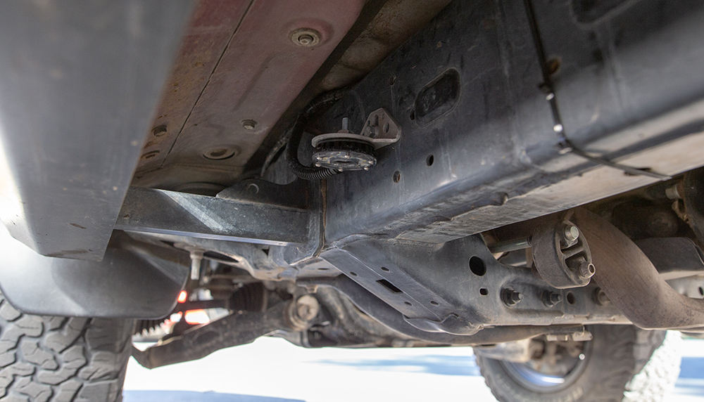
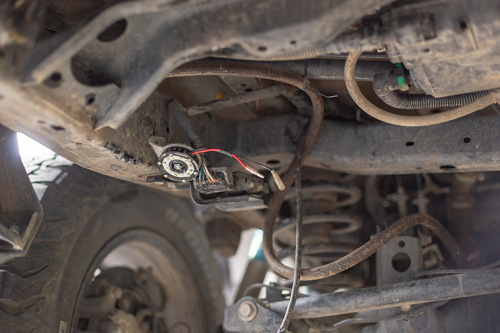
Step #16: Driver Rear Rock Slider Bracket
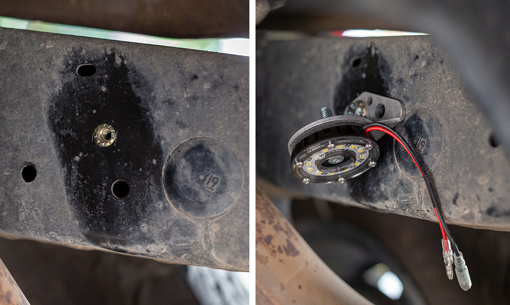
I utilized a threaded location on the rear of the frame to attach the rock light bracket.
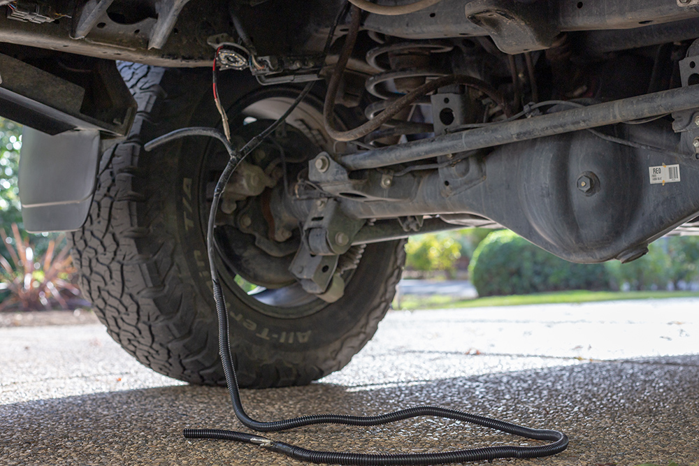
Step #17: Running Wires From Driver To Passenger Side
Double check to make sure everything is zip tied high up and to the frame. Not to moving parts such as the lower links or axel.
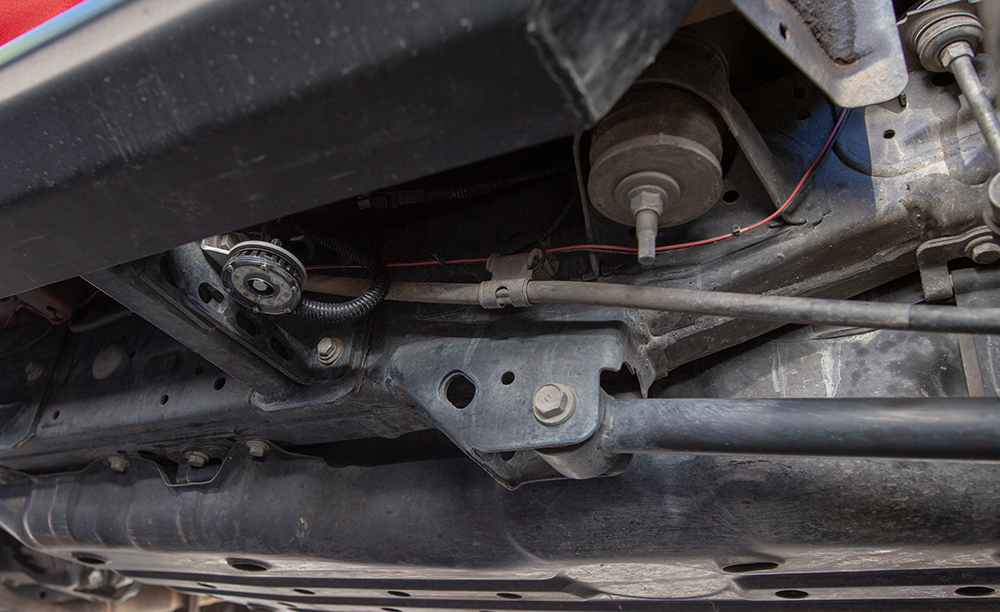
Step #18: Passenger rear Rock Slider Bracket
The driver side light attached to the frame rail, utilizing a pre-threaded location on the frame rail. To match the same location on the passenger side, while keeping a safe distance from the exhaust. I used a 6mm rivet nut with a 6mm bolt to attach the rock light bracket to the frame.
(Attaching a rivet nut)
Step #19: Cover Exposed Wires With Loom
Loom everything up, and zip-tie everything down.
Step #20: Check All Connections
Double check every connection, zip-tie, bolt, and light bracket from the engine bay to the back of the 4Runner. Correct and fix accordingly.
Hey Frank. Do you know if the lights are on a negative circuit? I see you trigger wire, is that a positive feed?
Yes, the wires were on a negative circuit. In the lighting diagram above, the lights were hooked up to positive constant, then grounded to turn on.
Do your rock light operate as normal as well? On and off with the switch?
They did with the rocker with I had installed. Since this post I have swapped over to a Switch Pros unit to control my rock lights.
with the new switch pros. Can you still make them courtesy lights or no ?
I just figured out how to do this yesterday! So to use it with the switch pros, you will need to have that trigger wire going into the switch pros unit, then in the switch pros settings, you will need to have that switch changed from “ignition” to “battery” power on in the settings.
Just to be clear…you are connecting a Switch-Pros trigger wire to PIN 15 of the FS1?
That is correct.
you can email me directly at fdrebelo@gmail.com and I would be glad to help you with the process.
Do you know what kind of current the dome light circuit can handle? I wired up 12 pod lights that draw a total of 3.6A, and I’d prefer to not squeeze another relay into my dash.
I do not know.
I Am working on this now and am curious as to how you count the wires when looking for pin15 of the fs1 connector in the A column? Also curious if you know if the 18’ has the same color dome light wire and if not, if you know of where I could figure that out?
This is the PDF that has the wiring diagram that I based this install off of. You can see the Pin 15 connector in Fig 21
http://toyotaparts.sparkstoyota.com/install/00016-00069-2017-4runner.pdf
Save yourself the headache and buy the bundle on this page. It works great and makes it super simple. Been considering doing a write up on it. https://dsimsolutions.com/pages/domerock-v4-bundles
Wow! That looks simple with the bypass connectors!
If I didn’t already have everything wired and just needed to tap, I would.
Do a writeup on it, man. Have you installed it yet?
yes, installed and really happy with it, makes it so darn easy.
Is there going to be an install writeup for this? Looks interesting.
I did a write-up for it but it was to similar to the instructions I had provided to DSIM which he published on his site. Unfortunately all his hosted pics are super blurry due to him using Photobucket so it’s hard to tell what’s going on. Write-ups on Trail4R need to be unique and not published elsewhere. I was hoping to completely re-do the write-up but haven’t had time yet.
Since this is tied into the dome light circuit do your rock lights come on whenever you turn on the dome light as well? Assuming the switch is set to auto of course? If yes, any dome light or just front ones or main one behind driver? Thanks!
Hey Mike, they do not turn on whenever I switch on the dome light from inside the vehicle, even when the switch is set to auto.
I have pulled the A pillar and I seem to have several green wires. Any more detailed info you can share.
Hi Dave, if you could, would you send me an email to fdrebelo@gmail.com with a photo of what it looks like, behind your A-Pillar, I would like to see if I can help you further. Thanks!
I’m looking at doing this but without the switch, just have them come on at unlock. Would you recommend using a relay or could I just wire the negative to the negative of the dome lights with constant power?
Adam, I think that they would be fine without a relay, and just wired into the negative of the dome lights. I have been running it like this for the past month or so with no issues.
Do you think this set up will work with the of rgb lights. I would like to be able to control the light intensity st the camp site.
I am sure it’s pretty dang similar. I don’t think the brackets come with the kit but it doesn’t matter, you can Zip Tie those lights to anything.
Any recommendations for sPod users? Would like to run this setup, but also have the ability to run them full time while on the trail.
As of now, I don’t have any recommendations for sPod users. This switch I am using is a SPDT (on/off/on) and to my knowledge, the sPod works as a SPST switch (on/off). So, I am not 100% confident this application would transfer over directly to the sPod system. Then again, I don’t have a sPod.
I want to do this to my 2001. 4runner so to be clear I just need to wire them up to the negative done light wire. Where do I get the power from? I want them light to come on when I unlock it. Thx for your help
In my scenario, the power came from the battery, and the negative trigger from the dome light completed the circuit. I would advise checking for a electrical diagram for the 2001 before embarking this.