
As an avid DIY project enthusiast, I am often seeking out custom projects that are just pure fun. Sometimes that means modifying my vehicle for the thrill of the project more than the necessity of the result. This rocker switch panel project was a bit of both.
I love my Switch-Pros 9100 system. It performs fantastically and reliably, but I did not have the foresight to plan for the day when I would use all the buttons on my system. So, this project came to life and allowed me to add a few more “luxury” items to my dash with super convenient access.
In all honesty, this guide is how I decided to customize this six-switch panel, but there are so many ways this could be utilized. If you needed all six switches, configure them so. If you need 6 USB ports, configure it so. If you like to talk to your passenger through a GMRS radio, throw in two handheld mic ports. The configurations are almost endless.
So, let’s jump right in with a good old-fashioned parts list and then talk through all the steps I took to transform my dash into what you see.
Table Of Contents
Installation
Tools and Materials:
- JB-Weld (Plastic)
- 6 Gang Switch Holder
- Blue Seas USB (typically $35)
- Blue Seas Rocker
- Amazon 3 Rocker Switch Pack
- Colored 16 Gauge Wire
- Jacketed 16 Gauge Wire
- Jacketed 14 Gauge Wire
- 14-16 Gauge Loop Connectors (switch pro/blue seas)
- Thick Heat Shrink
- Relay Holder
- 30A Relays
- Ethernet Passthrough
YouTube Install Part 1 – Relay:
YouTube Install Part 2 – Rocker:
Step 1. Remove Center Console Pieces & Shifter Knobs

First and foremost, we need to remove the 4×4 and drive mode shifter nobs. They unscrew just like any nut. In the photo on the left, the green rectangles represent the best areas I have found to pull or pry on the plastic. This is roughly where you will remove both interior plastic pieces to get at the interior plastic insert we want to customize.
In the photo on the right, the red rectangles represent things you need to unclip or remove. The two center red rectangles are the clip and electrical connector for the climate controls you removed in the left photo. The outermost red rectangles are the two screws that hold the plastic piece we will cut.
Lastly, the orange spots are where clips from the plastic insert will be anchored. Not necessarily important, but something I thought I would point out is that you will see them on the back of the plastic insert for the switches. (There is a tiny plastic piece in between the front cup holder and the future rocker switch panel plastic. Pull on it. It is held in by one clip.)
Step 2. Cut Upper Plastic Cubby With Dremel
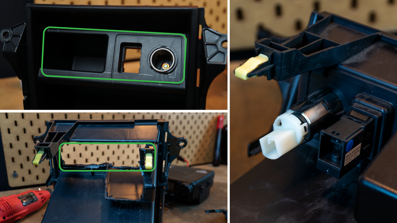
The majority of this opening will be cut out. I started by cutting horizontally right at the plastic bend on top and on the etched line below. For this, slow and steady was my motto as I can always cut more but not less. Also, I would recommend removing the cigarette lighter and USB/AUX ports before doing this. The USB/Aux is easy with the tabs on the back, but the cigarette port I ended up cutting out because I knew it was going in the trash.
Step 3. Trim Edges of 6 Gang Enclosure for Fitment

So this picture is pretty odd, but it’s to show that the ends of the six switch enclosure are trimmed. This is just slightly too long, and the corners don’t agree with the slanted plastic in the top corners, so make sure to trim this down with a Dremel so that it fits well.
Step 4. Jb Weld 6 Gang Enclosure to Trim Piece

Once your switch enclosure fits nicely, it is time to layer on JB plastic weld. It is linked above, but you apply it with a little piece of plastic or wood because it is quite thick. Hence, the messy application is shown above. The more the better here, as this is what will lock the enclosure into your stock plastic. This is especially true near the right edge because if you hit the plastic supports for that clip, you can easily repair it now.
Step 5. Insert Switches, USB, Blanks, Etc. Of Choice

Now is when you make the decisions. Do you want six switches? How about 12 USB outlets? The world is your oyster.
I chose to leave one spot blank for a GMRS radio port. Then I used one BlueSeas USB port, a BlueSeas rocker switch, and a three-pack of cheap Amazon-branded switches. I figured I would try some different switches out as well as show that multiple would work, depending on what people want to run.
Step 6. Make Custom Wiring Harnesses for Each Component
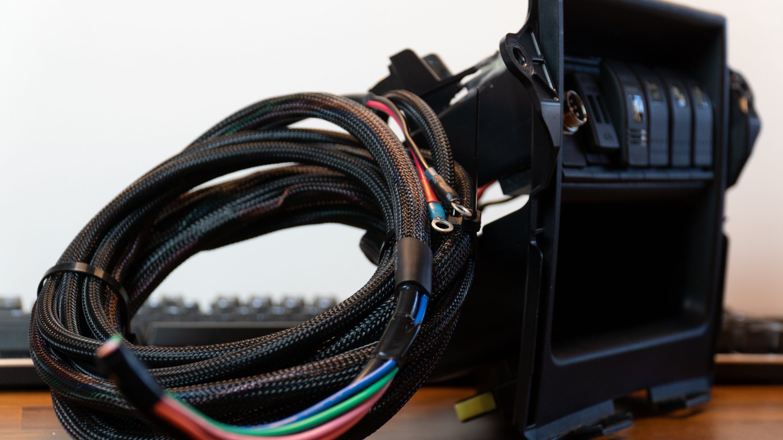
Now that you have chosen all the switches and ports for the front, it is time to make a wiring harness so you never have to remove this plastic piece in the future.
Step 7. Solder Wiring Harnesses to Electrical Inserts

For my ports, only 5 of them needed to enter the engine bay. For the USB, I wired it directly to my BlueSeas 6 fuse slot fuse box. The four rocker switches I wired up all have the same power and ground because they can share that power. Then, each switch has its own trigger output wire, which will connect to a relay and turn on the larger current flow to whatever we want to turn on.
Step 8. Remove the Head Unit to Access the USB/AUX wiring Harness

Next, we need to route the USB/AUX data cable to its new location before we put our plastic interior piece back into the vehicle.
This large, black, nicely braided cable is the one we want. It is held in place by these clips, along with them, which not only need to be removed, but they also take out the length we need in that cable to reach its new location. So, I cut the electrical tape and moved this wire around a few other harnesses to maximize its length.
Step 9. Remove the Plastic Panel Right of the Steering Wheel

Removing the plastic is quite simple; the hard part is just getting some leverage to pull. It is held in with four red clips and pops out pretty easily.
Once removed, you will need to shave the side off one section of the USB/AUX port. It has this sort of “puzzle piece” cut out, and it does not technically fit, but everything will still latch into place fine. Once you click the port into place, your cable can be routed behind this plastic panel and plugged in. There is not much slack, but it is doable.
Step 10. Relocate Usb/aux Stock Port

With everything routed, the port fits nicely, and the label still even works!
Step 11. Route Wiring Harnesses to Engine Bay

Passing wires through the firewall can be challenging, especially when you may have an amount as I do in the way and plenty of other wires passing through. In hindsight, I would have just removed this completely, but since it was winter, I gave it a shot and ended up spending 30 minutes passing the wires through.
A tip I received was also to cut a small “X” in the rubber grommet, especially in the winter, and this will save a lot of headaches while not really impacting the grommet’s ability to keep out dust.
Step 12. Connect Wire Harnesses to Fuse Box & Relay Holder

For my case, I connected my USB ports directly to the fuse box so they are always on. Once I did this, I went and plugged in my phone to make sure everything was working properly.
After that, one would connect all their trigger wires to the appropriate relay. Being that I already have a Switch Pro system, this was more for expanded switching capabilities in the future. That being said, I need to tear everything out and rework a mounting solution to fit a generic relay box in here with my Powertrays setup. I did not connect any wires to relays, but I will probably do a future article on my relay system setup.
There are plenty of good resources out there for how to wire relays and what many people do to mount a relay box without a Powertrays in the way, haha.
Step 13. Zip Tie Wires Neatly in Engine Bay/ Mount Relay Holder/box

This is the relay box I might buy. Another good option is the Bussmann RTMR 15303-2-2-4. Wanderlost Overland has done a nice job laying out that wiring project on their YouTube channel. Both have a fuse box built into them, and it should work quite well with my application.
Final Thoughts

Assembly works the same as disassembly, just in reverse order. This rocker switch panel project took a lot of thought and planning to execute, but the actual process of doing it was quite seamless. Half the work was sourcing all the right components, preferably from easy areas for many people to purchase. I love the look, and it utilizes a space that otherwise is wasted, as far as I’m concerned.
If you like video-style installs in addition to photos, check out the videos I linked above because I filmed these installs on my YouTube channel.
Thanks for reading. Check me out on Instagram and YouTube for other awesome mods and projects I have done.
I’ve got that relay box. It’s kind of crap, to be honest. Was an absolute pain in the ass getting anything other than 14ga wire into it from the underside. I’ve been looking at either a Bussman or designing and 3D printing my own when I do the second version of my power distribution box
Excellent install and write-up I’ve often thought that would be an ideal location for additional switches and location for radios.