
Factory Looking Switch for the 4Runner – Cubby Mounted S-Tech 12-Circuit Dual Push Switch System Installation Guide and Review
If you’re looking for a large number of switches in your 4Runner, this 12-circuit switch from S-Tech Switch might be for you.
It features two 6-circuit power distribution control modules pre-equipped with relays, fuses, harnesses, a voltage protection module, in addition to the circuit breakers, and a clean row of cubby-mounted dual-switch push switches.
The two power distribution modules tie into the 6 dual push switches mounted into a 3D-printed housing that bolts to your factory center console plastics. The front of the housing is offered in matte, carbon fiber, or a textured finish. They provide two 60AMP circuit breakers, a 12-volt cutoff module, extra braided sleeve power leads, hardware, brackets, and more. I think the biggest selling point of the S-Tech system though, is that it looks more factory than the competition.
While most of the competitors have cool switch panels, they leave it to you to figure out where to mount them. And, with something as big as 12 circuits, the switch panels are massive. S-Tech Switch is known for the most “OE” looking switch panel systems on the market and they definitely nailed it with this cubby-mounted switch on the 4Runner.
Find it Online
- 12-Circuit Cubby Switch Panel: Check Price
- View all switch systems: Check Prices
There are systems for any price range, from 4 switches up to 12. You can buy a complete kit or get one of their custom housings and use your own switches and wiring. S-Tech can make a one-off system for your specific needs or the standard systems for a more affordable price. They also offer a variety of options for the 4Runner, Tacoma, Jeep, along with other makes and models.
Features & Benefits

One of the most obvious benefits is that you can control lots of auxiliary lights.
Other Features and Benefits:
- 5-year warranty on all systems
- Circuit/relay capacity: 40 AMP Relay / 30-35 AMP Recommended / 600W Maximum
- Custom Switch Housing mounts with an OEM look
- Easy Installation
- Available in Matte, Carbon Fiber or Textured
- The system includes fuses and relays
- Operating Voltage: 12V. Max Wattage: 600 Watts. 40A max on a single circuit.
- Integrated Amp / Voltage protection to thermally protect your lights and accessories
Tools and Materials
You need standard electrical tools for this one. Nothing too special.
- S-Tech Switch
- Overland Equipped Tray
- 2 X 60AMP (or higher) breakers)
- Blue Sea Breakers (Recommended)
- 6AWG Wire
- 8AWG Wire
- 12AWG Wire
- 14AWG Wire
- 16AWG Wire
- Waterproof Connectors
- Heat Shrink
- Braided Sleeve
- Heat Gun
- Pliers
- Socket set
- Klien Crimpers
- Klien Strippers
S-Tech Switch Install & Review
Kit Contents
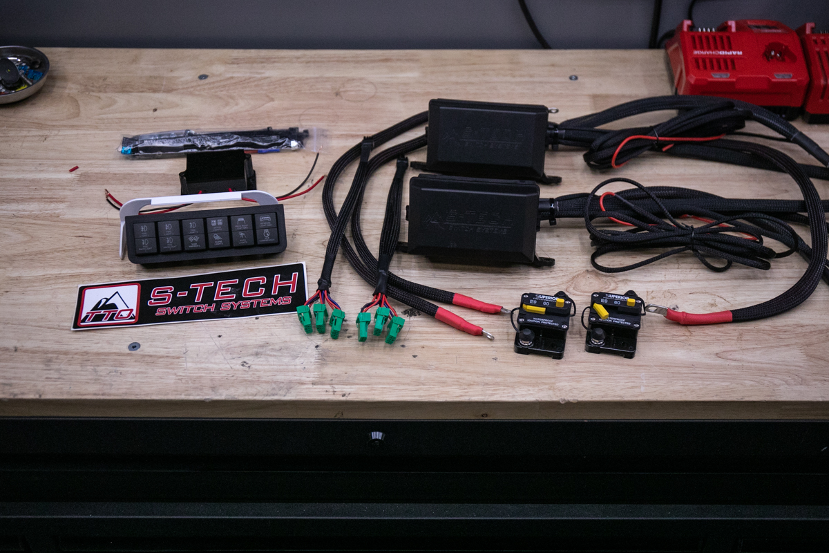
The kit comes with everything that you need to install it, however, depending on your installation, you may need to adjust the length of the harnesses. With that in mind, it’s best to be prepared with all the electrical supplies you think you might need.
Kit Contents:
- 2 X 6 circuit/relay modules
- Capacity: 40 AMP Relay / 30-35 AMP Recommended / 600W Maximum
- Modules include fuses and relays (can be replaced and moved around)
- 6 X Custom-printed dual push buttons
- 12 total circuits
- Custom switch housing with an OEM look
- Available in Matte, Carbon Fiber, or Textured
- 2 X 60amp breakers
- 12V circuit cutoff
- All power, ground, ignition, and switch leads
The only thing not provided is a power module and breaker mounting tray.
Switch Module Overview

Here is an overview of the switch module. This is one of the two, 6-circuit/relay modules that will come in your kit. Like most switch modules, they come equipped with relays and fuses pre-slotted. You can easily swap out both the fuses and relays if you overload any circuit.
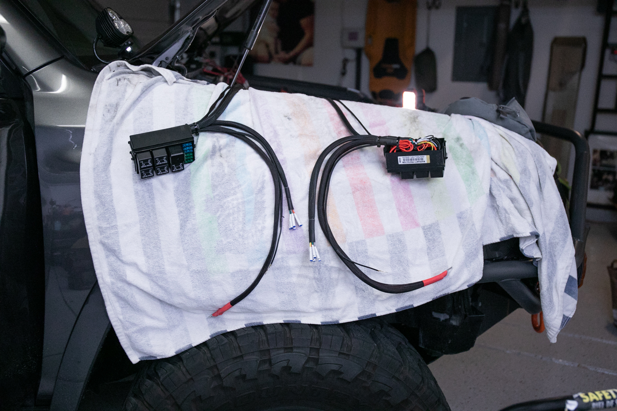
Wiring Overview
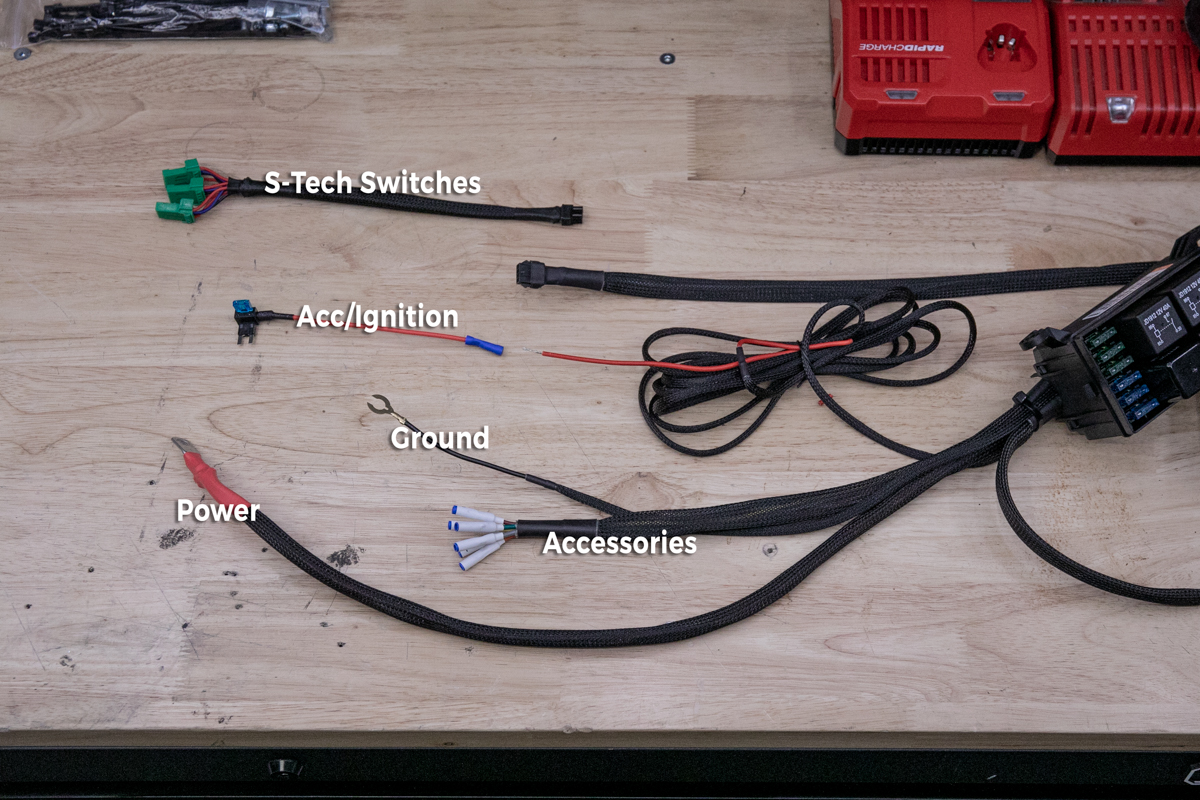
Here is an overview of the wiring from the switch module. The S-Tech switch leads and the ignition leads will need to be connected to their respective lead.
Step 1. Determine Mounting Solution
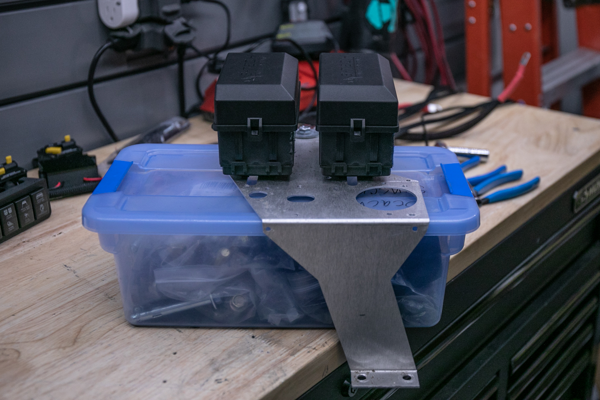
For mounting both our switch modules, I used a tray from Overland Equipped.
Step 2. Cut off Mounting Tabs on Switch Modules

In order to gain more clearance all the way around the modules, I cut off all the unneeded tabs.
Step 3. Connect Bottom Plates
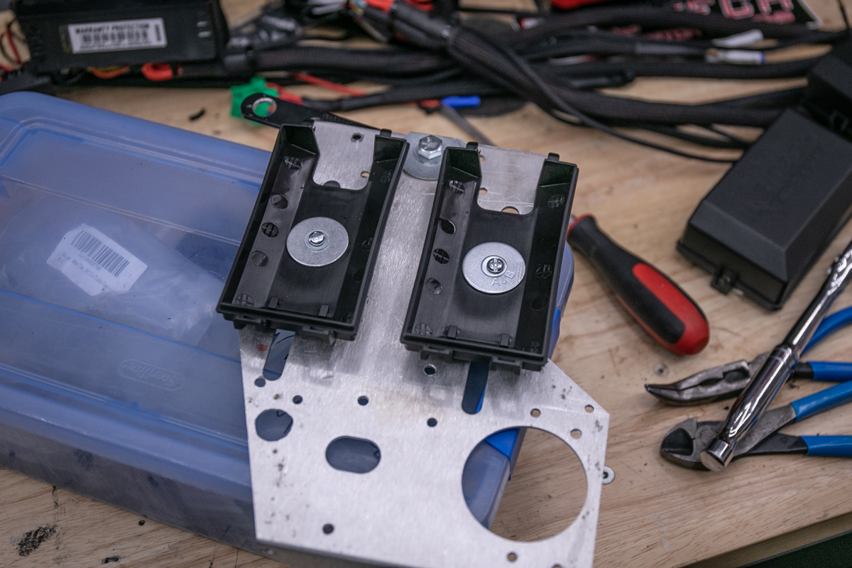
I attached both modules by hard-mounting the bottom of each module with oversize washers to ensure a solid mount.
Step 4. Mount Breakers
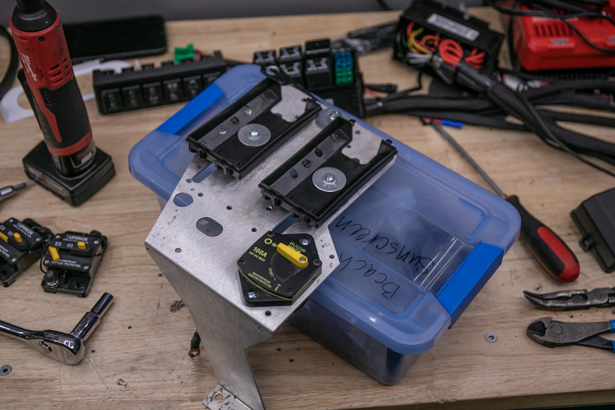
For breakers, I re-used the 100Amp Blue Sea Systems breaker that was previously on the Overland Equipped tray and then used one of the 60Amp breakers provided in the kit.
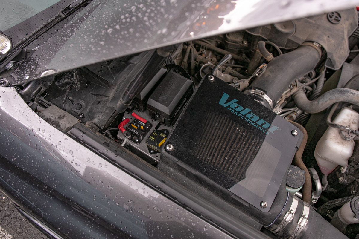
Step 5. Determine Mount Location
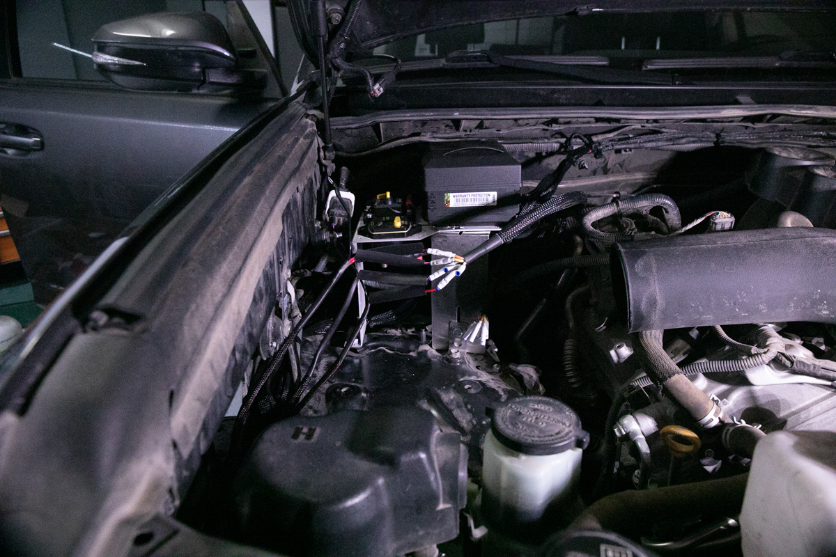
I decided to mount the tray on the passenger side in between the firewall and the air intake airbox. For the other leg on the tray, I used the mounting bracket from a switch-pro kit for the Overland Equipped tray to support both S-Tech switch modules and the breakers. If you don’t have a Switch-Pro on hand, you can get a flat piece of steel/aluminum and bend it with a vise. Alternatively, just Google “10 x 6-inch angle brackets” and find something stout that works for your setup, which you would have to modify as well. You can also get creative with almost any tray for the 4Runner. I recently wrote a post on the top switch and compressor mounting trays for the 5th Gen 4Runner. You might find something over there that works better for you.
Step 6. Passenger Firewall

If you’re mounting the modules on the passenger side, it makes sense to run the wires through the passenger firewall.
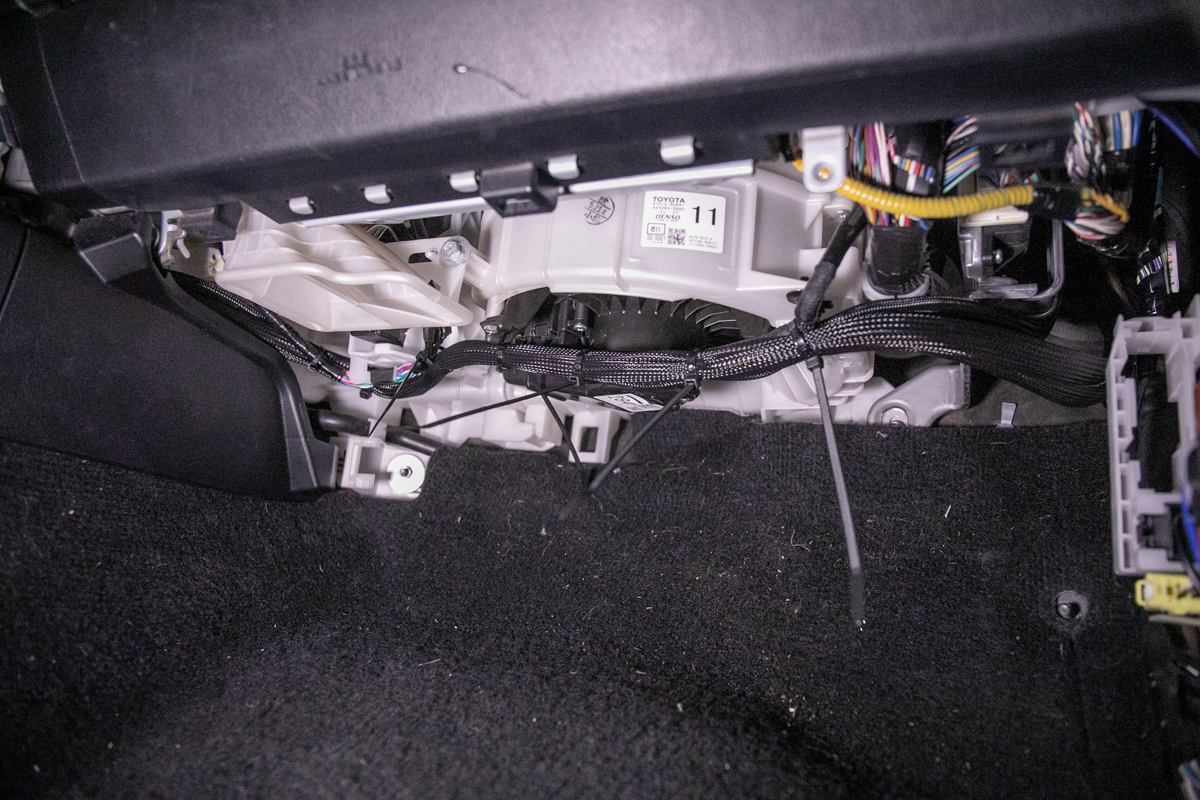
Step 7. Remove Plastics In Footwell

Remove this plastic trim piece under your glove box in the footwell to gain more access to the firewall passthrough point.
Step 8. Prepare Harnesses
I let both modules hang on the side of the fender while I fed the ignition wire and switch wires through the firewall. This is also helpful for positioning the mounting tray in place before bolting everything down.
Step 9. Ignition Wire

Connect the Ignition leads from both modules into one harness and then run that harness over to the ignition Add-A-Fuse.
Step 10. Ground Wire

Connect both ground wires from both modules into one lead. You can run this lead over to the battery or your preferred ground location of choice.
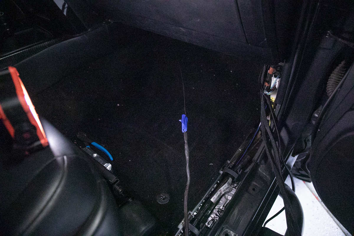
Step 11. Switch Wires

Run both of the switch leads up through the dash near the cubby. You will connect these to the push switches once everything is getter closer.
Step 12. Zip-Tie Ignition & Switch Wires
Once you have all the wires pulled into the cabin through the firewall, proceed to tighten up all the slack under the dash and the center console. Now loosely zip-tie everything down to an anchor point.
Step 13. Connect Power Leads to Breakers
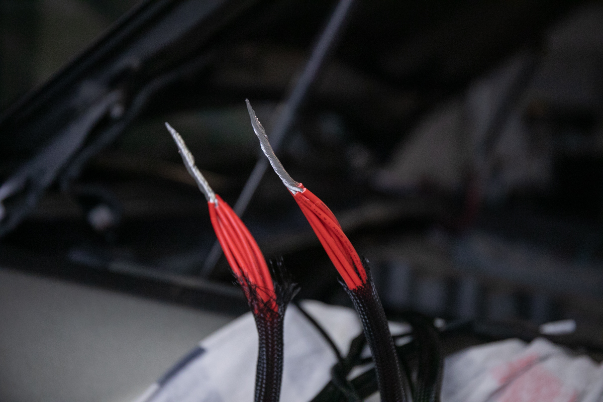
Cut down both power leads from the switch modules and connect each lead up to each breaker.
Step 14. Connect Power Leads From Breakers to Battery
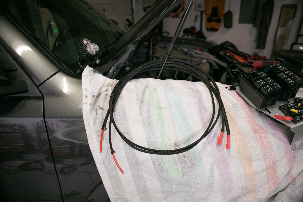
After the switch modules are connected to the breakers, build longer 6AWG-8AWG power leads that will connect from the breakers over to the battery.
Step 15. Remove Center Console Cubby

Remove your center console cubby (Lower Panel Knee Bolster).
Step 16. Drill Holes in Cubby
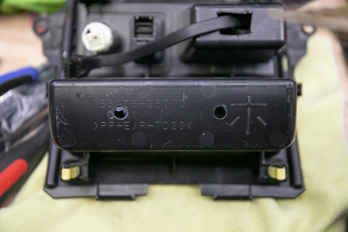
Using a step bit, drill two holes in the back of the cubby in order to make room for the two separate switch leads that power the main switch panel.
Note: I removed my old switch and bought a new cubby plastic piece so that my top cubby was whole again.
Step 17. Mount Switch in Cubby
Connect both switch leads to the switch panel and install the switch.
I did not need to drill holes in order to mount the switch panel bezel with the small screws provided. The switch panel bezel fits extremely tight in the cubby and is almost impossible to get out once it’s firmly pressed in place.
Step 18. Mount Cubby in Dash
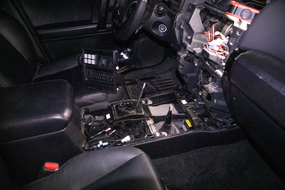
Once the switch leads and ignition leads are in place, you can connect the switch, and install the center console cover/cubby plastics.
Step 19. Connect Power & Ground
Finish your installation by running power and ground to the distribution modules.
Connecting Accessories
I connected all my accessories directly to the switch accessory leads provided. If you would like to make each lead serviceable or you plan on changing your build around a lot, you can use Deutsch connectors instead of using the provided crimp connectors. I have Deutsch connectors on all my harnesses connected at my bumper. I am a big fan of using Deutsch connectors and Weather Pack connectors, however, my build lighting is perfectly set up on the bumper so I won’t be changing out these leads. I also have three open switches on my Switch-Pros so if I ever add anything in the future, I will connect something on the driver side.
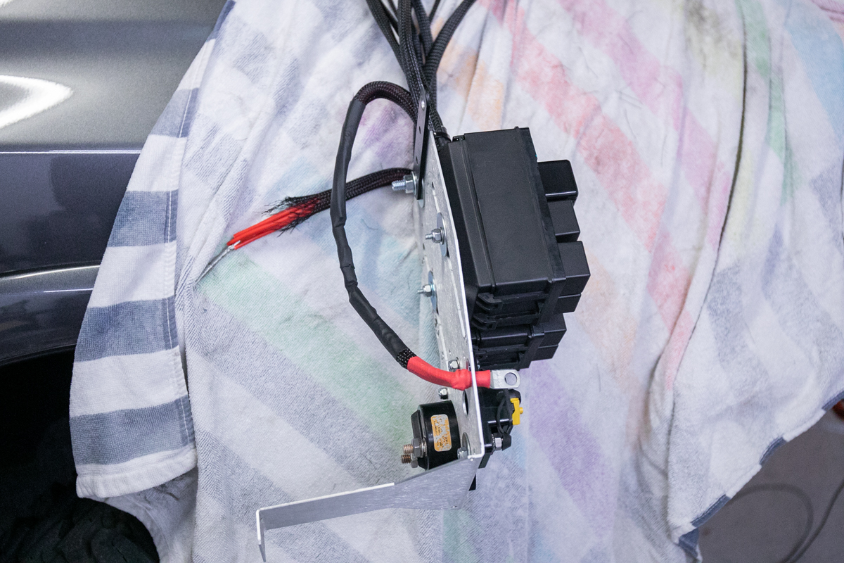
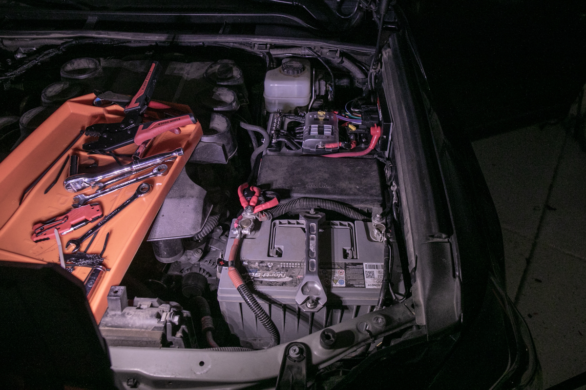
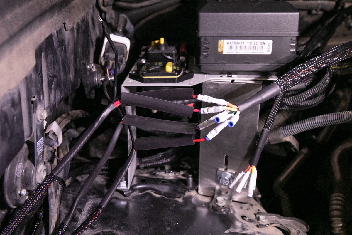
Power Distribution Modules
Here is a look at both power distribution modules mounted on the tray with both breakers tucked behind the air intake air box. There is just enough room to pull the cover off the back module in order to service the fuses and relays. The tray fits perfectly back here but it would have been nice to have a solution out of the box from S-Tech. Something to consider.
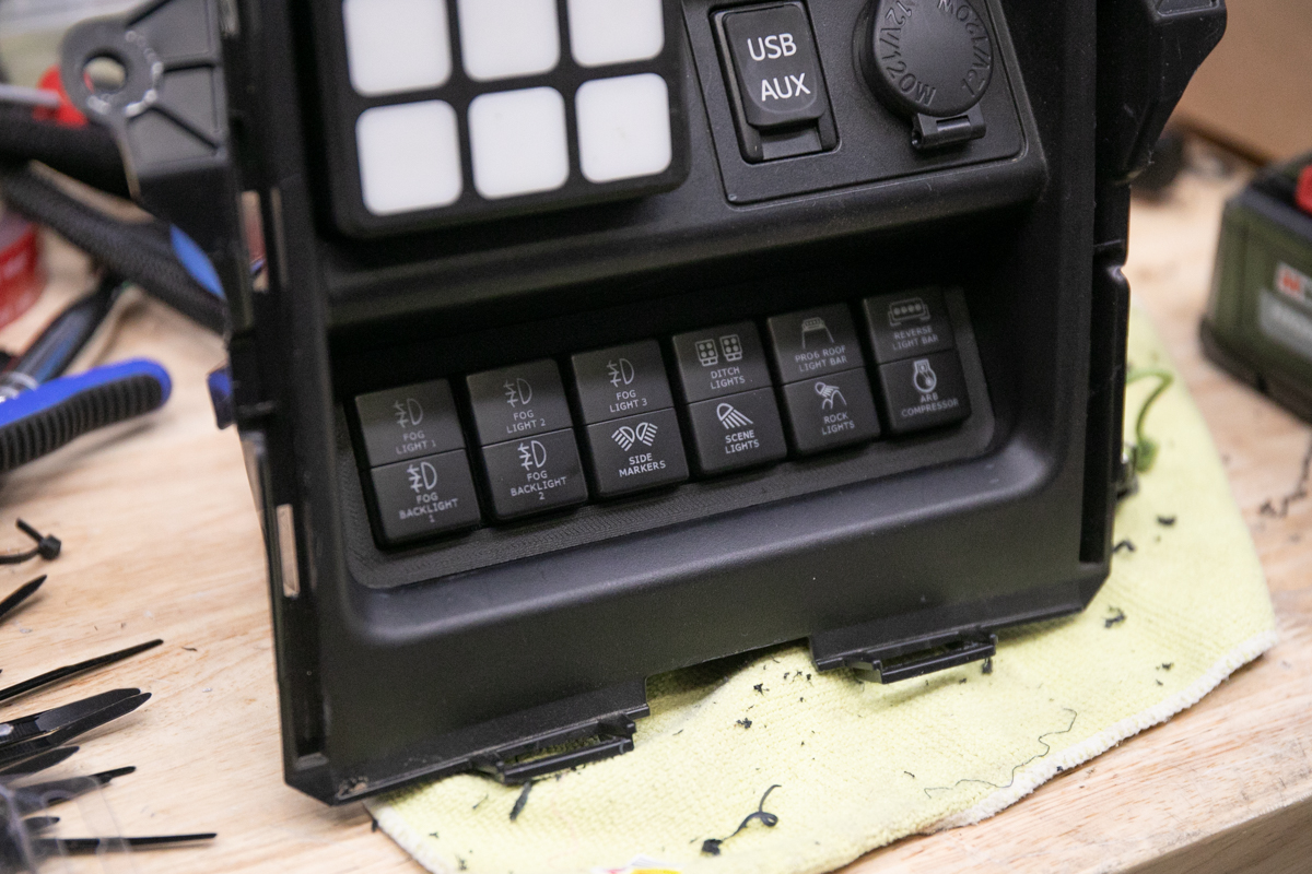
Switch Panel
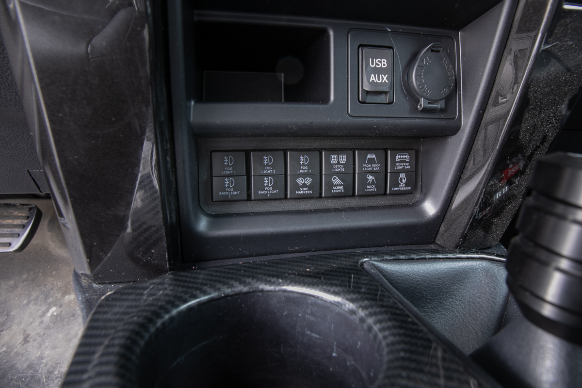
What matters most is how it looks in the cabin and I can tell you right now, this is the best-looking switch I’ve ever installed. After three (3) switch-pros and a couple of Auxbeams, nothing looks as factory as this S-Tech switch. Very clean/factory look in the cabin.
Why So Many Switches?

I have over 30+ KC Lights and other selectable mods; onboard air compressor, winch, rear cargo space 12v mods, etc.
What really starts adding up are the lights that feature both a full power mode and DRL/backlight mode. For just my forward-facing lights (bumper, ditch, rock, and rack) alone, I need 11 selectable switches. I’m also running scene lights, chase lights, under-hood lights, and other interior lights as well. All in all, I am currently utilizing 17 switches in addition to all 6 circuits being used in my 6-circuit fuse block.
Review
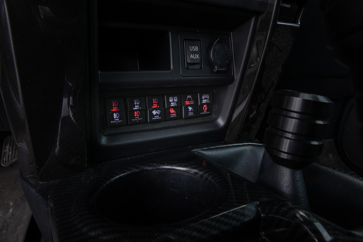
There is currently no solution that offers upwards of 20 switches to control a full build which is why I decided to run the S-Tech 12-circuit switch in addition to the SP 9100. Switch-Pros makes an RCR Force 12, however, there is no clean OE look to mount two back-to-back RCR Force 12 systems.
The S-Tech 12-circuit switch offers a very clean OE look when positioned in the cubby. The biggest selling point of this switch system is how good it looks when mounted in the cabin. It looks and feels like a factory add-on.
So what’s the challenge with this switch?
First, there is no plug-and-play module mounting solution in the engine bay. You need to get creative on how you mount your power distribution modules. Second, the two modules create a ton of wires. It would be very nice to get both modules condensed down into one unit, one power lead, one ground, one ignition, etc. I think the interior appearance outweighs those two challenges though.
At the end of the day, I think this kit is a great option for someone looking for 12 OE-looking switches.