
There are plenty of rear bumper options for the 5th Gen 4Runner, but none of them grabbed my attention—until Dissent Off-Road entered the game. I sought something that offered solid protection and utility while enhancing my rig’s overall aesthetic. The Dissent bumper’s high-clearance angles and sleek, aggressive look were exactly what I wanted.
Check out Brenan’s article for an in-depth breakdown of its construction and features. This is a must-read if you are considering a rear bumper for your 4Runner.
In this article, I’ll focus on the installation process. From the prep work to the final adjustments, I’ll guide you through how to install this at home and save some labor costs.
Find It Online:
- Modular Rear Bumper: Check Price
- Swing-Outs: Check Price
Table Of Contents
Installation

Installation Video
Difficulty
- Moderate to Hard
Time & Assistance
- Hours: 4-8
- People: 3 (ideally)
Tools & Materials Required
- Socket Set – 10, 12, 13, 15mm + 1/2″ & 5/16″
- Wrench Set
- Ratchet – 3/8, 1/2 inch
- Impact Wrench
- Tin Snips
- Pliers
- Seam Sealer
- Black Paint
- Angle grinder
- Sawzall
- Anti-Seize
- Electrical Tape
- Soldering kit
- Heat Shrink
- Heat Gun
- Voltmeter
- Rags
Step 1. OEM Bumper Removal

Remove the (9) 10mm bolts indicated above; there are also some inside the fender wells.

Wiggle the bumper from both sides, and it should pop right off. While you’re at it, remove the rear mud flaps! I also removed the spare tire to create more room for this installation.
Step 2. Sheet Metal Trimming

Use tin snips to trim the necessary areas of sheet metal. Focus mainly on the corner, as shown in the picture above. Cut up to 1.25″ further back for larger tires or trim as needed. Once cuts are made, use pliers or hand seamers to fold the sharp edges in the wheel arch. Finally, touch up any fresh cuts with paint to prevent rust. I also used some seam sealer.
Step 3. Modify Trailer Plug Harness

Remove the electrical tape and unbundle the trailer plug to maximize wire length.

Then, cover the exposed wires with a wiring loom to protect them.
Step 4. Remove Keyless Entry Antenna

If your 4Runner has keyless entry (later models), loosen the antenna and let it hang for now. Ensure to restart the bolt underneath to avoid losing it.
Step 5. Remove/Bend Brackets

Remove or bend the indicated brackets upwards to make room for the bumper shell. I used a hammer to bend them upwards enough so they would not interfere.

The above photo is what they should look like after being bent.
Step 6. Remove Spare Tire bars

Remove both the spare tire bar hoops. We used an angle grinder to cut them off.
If you have any other brackets, such as rock lights bolted onto the rear cross member, remove them as well.
Step 7. Prep Rear Cross Member (Weld-In Hitch)

Mark a straight line roughly a quarter inch inwards from the factory hitch frame nuts on both sides and mark another line roughly 1/8” below the radius from the top of the cross-member.

This is where things get serious: removing the frame tab. Dissent suggests using a saw or plasma cutter, but we managed with an angle grinder.

Note: Avoid cutting the internal weld nuts or the frame’s round tube. Cut just under a 1/8″ from the nuts.
Step 8. Install Weld-In Hitch (If Applicable)

Next, we installed the weld-in hitch using the factory M12 bolts. Once secured, it was time to weld it in place. We made sure to grind off some paint from the cross-member where the welding needed to happen.

A fresh coat of primer and paint later, and boom—weld-in hitch done and dusted!
Step 9. Install Wing Stiffener

Install the wing stiffener using (3) lower M8 bolts on each side. They have an offset; make sure the side where the gusset is closer to the edge goes towards the front of the vehicle.

Align the stiffener front to back using the provided holes, centering it before tightening. Don’t use any bolts in the centering hole. If necessary, grind down any welds to ensure a flat surface for the wing stiffener installation.

Install the top clamp bracket on the cross member, clamping it tightly using the 5/16 bolts. Make sure the larger portion of this bracket is towards the rear of the vehicle, the smaller part is towards the front of the vehicle, and the bracket’s tabs are keyed into the wing stiffener pieces.
Step 10. Position Bumper

Insert the provided spacers according to your hitch configuration. For the weld-in hitch option, use (1) rectangular spacer. Install the factory hitch hardware (M12) on top, but keep them loose so the bumper shell can slide on top of the spacer into the bolts. Ensure the trailer wire harness sits on top of the rear cross member.

Note the correct orientation above for the weld-in hitch configuration.

Begin mounting the bumper by slowly sliding it over on top of the rear cross member. Loosely install the M8 bolts underneath on the wing stiffener side. Use (1) M12 bolt on the underside and (2) M8 bolts, as highlighted above. The torque specs for the M8 bolts are 25 ft/lbs, and for the M12 bolts, they are 70 ft/lbs.
Repeat the process for the other side.

Next, install the hitch cover plate. While pushing the hitch cover down from the top on the cross member, install the (4) M12 bolts and tighten them to 70 ft/lbs. Next, move on to the lower M12 bolts; these are bolted from the bottom of the hitch into the bumper assembly.

Then, install the (4) Grade 8, 1/2” bolts on top of the hitch cover plate and tighten them to 90 ft/lbs.
Step 11. Install Nut Plate

Insert the nut plate into the access hole, aligning it with the frame. The nut plate’s ear should fall into the square hole in the bumper shell on both sides.
Once finger-tightened, use an M8 bolt and torque to 25 ft-lbs to secure the bumper in place. Remember to do the same on the other side as well!
Step 12. Reinstall Keyless Entry Antenna

I reinstalled the keyless antenna bracket at its factory location, slightly bending it out of the way to ensure clearance. I pulled it downwards until it was not touching the bumper.
Step 13. Trim Plastic Bumper Cover

Measure the distance from the top of the bumper sides to the top of the black plastic locking strip for the factory bumper. Note the measurement and reduce it by 1/8” (7 3/8” in my case) for your cut line.
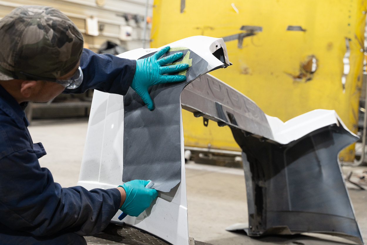
Mark the provided template on the other side of the bumper. Using masking tape, make a straight line joining both these points.

After you make your first cut, place the bumper cover on your 4Runner and check fitment.

Use a washer or a similar tool to measure a half-inch gap from the Dissent bumper to the bumper cover, giving your final cut line. Once done, apply weather stripping along the cut edges. The bumper cover should not make contact with the Dissent bumper.

For tight corners, make a V-notch in the weather stripping for a snug fit, cutting away any excess material.
Step 14. Install Dissent Combo Lights (Optional)

You have a few rear bumper light options, but I chose the Dissent Combo Lights because I love their Aussie-style look. Also, since the spare tire carrier may obstruct the factory tail lights, these combo lights serve as a second set of tail lights.

First, remove your tail lights and disconnect the wiring harnesses behind them.

I extended the wires to about 3 feet on the Dissent lights and tapped them into the factory tail light wiring. They recommend using 18-20 gauge wire for this.

I used the factory grommet (shown above) to route the wires inside the vehicle. Then, I tested the wires individually to identify the correct connections for Reverse, Running, Signal, Brake, and Ground on both sides.

Since the color coding varies, I’ve saved you the headache by providing the correct wiring details above.
(Note: My 4Runner is a 2021 TRD Off-Road Premium, so your vehicle’s wiring schematic might differ.)

After identifying and tapping into the wiring, I soldered the connections and used heat shrink tubing to secure everything. I reinstalled the factory tail lights once all the connections were tested and solid.

Finally, I fastened the Dissent Combo Lights to the bumper using the provided Allen head screws and plastic washers. I opted for the smoked-out lens for a sleek finish.
With everything in place, these lights enhance the look of the rear bumper and add extra safety and functionality to my rig.
Swing Arm Installation (Optional)

This section will cover their assembly and installation if you opt for swing-out arms and accessories.
Step 1. Prep Swing-Out Arms

The UHMW plastic piece is bolted to the bottom of the swing-out arm, which will rest on top of the striker plate. Use the button-head sockets to bolt it to the swing-out and the lock nut on the other side.

Then, install the gas strut spring bracket, as shown above.

Next, install the ball stud in the outermost location for the gas strut assembly.
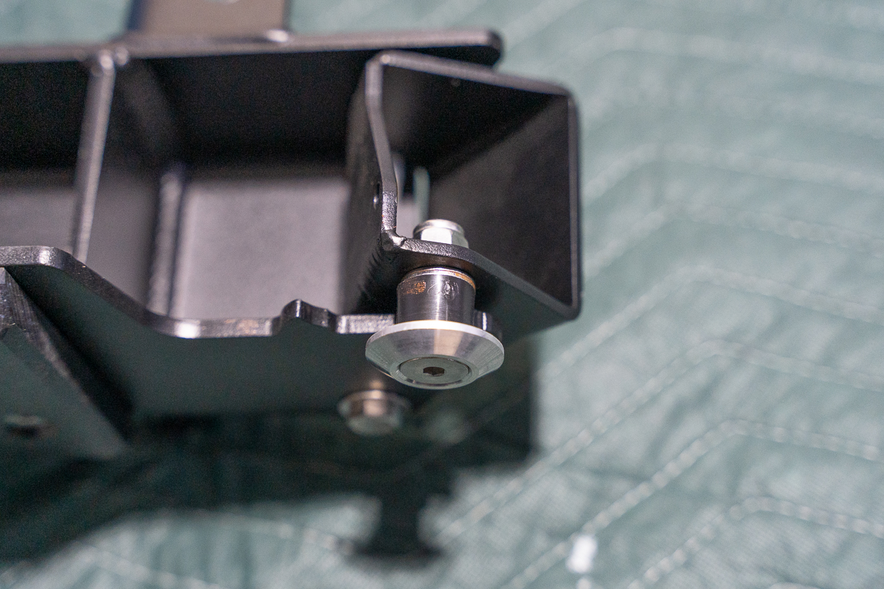
The striker pin mates with the striker pad and keeps the swing-out in place when latched properly. Install the striker pin on the latch portion of the swing-out, as shown above.

Finally, install the spring as shown above.
Step 2. Install Striker Plates

Install the striker plates on both bumper ends (if you opt for dual swing-out arms).
Step 3. Preload Setup For Swing Arm

Begin by spacing the gap between the striker plate and the swing-out arm with a fender washer on the tire carrier side. This setup helps account for the tire’s extra weight. If you’re installing a Jerry can or ladder on the opposite side, you may need to adjust the preload accordingly.

Aim for a small gap, as the tire’s weight will align everything once installed.
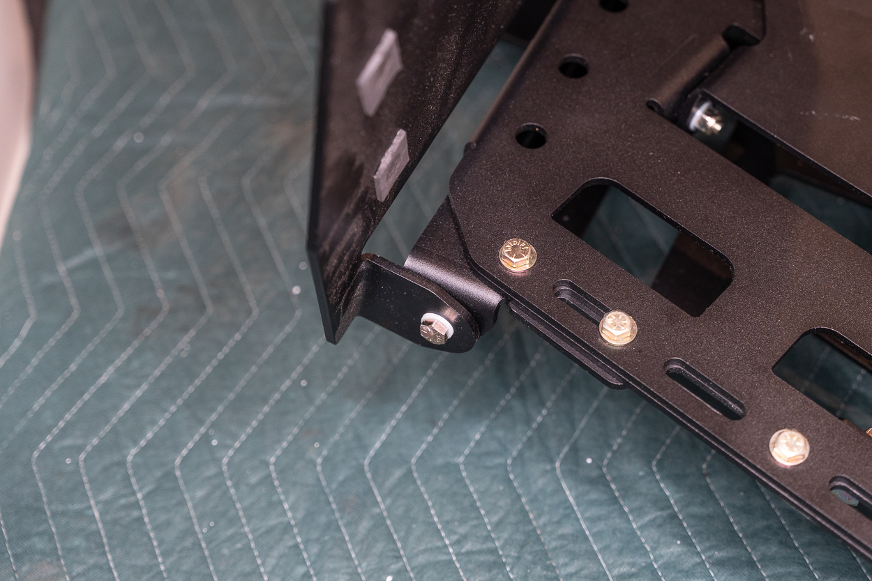
Step 4. Bolt Alignment

Start by inserting the bolts on the outer side of the swingout. Use an extension with a slight swivel head to ease socket placement if available. Adjust the swing arm’s position by moving it left and right until it is centered. Snug up the outer bolts, but leave them slightly loose to adjust the alignment later.

Next, open the swing arm to confirm the alignment, then secure the remaining bolts. If the bolt holes don’t line up, loosen and readjust the swing arm until the bolts fit. The torque spec for these (4) bolts is 52 ft/lbs.

Tighten the top bolt with a crescent wrench or a 32mm socket. There’s no exact torque specification, but you’re aiming for a slight drag on the bearings without over-tightening.
Note: Apply a generous amount of anti-seize to the 7/16” bolts. This helps prevent rusting, as the interior threads of the bumper’s weld nuts are not coated.
Confirm that the gap under the striker plate pad aligns as you add the spare tire. The pad should touch the striker plate without forcing it over. Adjust the shims as necessary to ensure the pad lightly rubs the striker plate without excess resistance.
Step 5. Setting Bump Stops

Each swingout is supplied with (2) bump stops: one small and one large.

The larger bump stop is preferable for the tire carrier swingout, though a smaller one with additional fender washers may work if there is too much resistance.

For the other swingout (ladder/jerry can), you can set a looser preload to reduce the amount of force needed to close the latch. Hence, use the smaller bump stop on the inside and the larger one on the outside. You can use the supplied spacers with the smaller bump stop to adjust the preload to your liking.
Note: Do not install the outer bump stop until the gas strut is installed. Doing so will limit the full extension of the swing-out arm, which is needed to install the gas strut.
Step 6. Install Gas Strut

As shown above, install the second ball stud on the bumper near the bearing assembly.

As mentioned earlier, leave the outer bump stop off to allow full swing arm extension. Align the strut end on top of the ball stud, then press the gas strut into place. This shouldn’t feel forced.
Repeat for the other side.

Next, install the outer bump stop. Once in place, aim for a maximum extension of 6-3/4″ to prevent the strut from overextending. You may need to add washers behind the bump stop to reduce the distance.
Tire Carrier & Table Assembly (Optional)

Dissent Off-Road has smartly integrated the tire carrier and table into a single design, creating a clean and functional setup.
Step 1. Attach Table Leg

To avoid scratching the powder coat, install each table leg with (3) nylon washers per bolt: (1) by the bolt head, (1) between the leg and the front riser, and (1) before the nut (shown above).

Next, insert the table leg into the divots on the riser, placing nylon washers between the table leg and the riser divots.
Tighten the bolts and nyloc nuts until the leg can move smoothly with a slight resistance.
Step 2. Reinforce Riser Legs

Attach the reinforcement plates to the riser legs using (1) 1/2″ x 1-1/4″ bolts, each with washers and nuts. Keep the bolts finger-tight for final adjustments later.

Temporarily thread a bolt through to align the plates, then tighten the upper (2) bolts to 85 ft-lbs.
Step 3. Install Front Riser

Slide the front riser into the rear riser and align the bolt holes along the edges. Secure both with (6) 5/16″ bolts (top-down) and washers into the smaller hole cutouts. Install nyloc nuts on the bottom bolts but leave the top two off to install the table hinges in the next step.
Step 4. Attach Table Hinges & Latch

Flip the assembly over, align the hinges with the top bolts (2 on each side), and secure them with washers and 5/16″ nyloc nuts.

For the latch assembly, apply anti-seize to the bolt, insert it through the latch with washers and a nylon spacer, and tighten with a nyloc nut until it’s resistant but still movable.
Step 5. Mount The Table

Cover the bolts on the front riser, then set the table.
Lift the table’s corner with the hinge bracket, and install a 5/16″ bolt with a nylon washer. Then, place another nylon washer on the other side of the hinge and a third on the bolt end.
Finally, tighten the nyloc nut.
Step 6. Apply Foam Padding

Cut a 1″ square from the included foam strip and apply it to the table leg end, aligning with the front riser. Apply two longer foam strips to the bottom of the table near the bolts on the risers. Finally, add another 1″ foam square to the top of the table leg, aligning it with the latch. Remove the film and press firmly once all the foam pieces are in place.
Step 7. Install Tire Clamps

Install the swatch plate using the short 1/2″ bolt and nut with the washer on the inner clamp as shown. For now, keep the bolts finger tight.

Position the outer tire clamp on the far right of the riser, aligning it with the bolt hole.

Position the inner clamp so its groove matches the outer clamp’s, and finger-tighten both clamps to the riser. Flip the assembly, and finger-tighten both clamps on the front riser. Adjust the clamps as needed for tire position.
For this step, you will use the 1/2″x 1-1/4″ bolts and 1/2″ nut with the washers.
Step 8. Install Tire Mount

Insert the tire mount between the clamps, threading a 4″ bolt.

Next, insert the second lag bolt through and add washers and thread nuts on the bolts. Keep everything snug but not super tight, as the final adjustment will happen when you attach the tire.
Step 9. Attach Tire Carrier Assembly To The Swing Out

Place the entire tire carrier and table assembly on the swing-out arm. Fasten the tire carrier assembly to the swing-out arm using the (3) 1/2″ bolts and nuts. Then, torque them to 85 ft/lbs.
Step 10. Install License Plate Mount & Light

Attach the license plate brackets to the spare tire swing-out mount using the included hex button head screws and nuts with washers on the other side. Next, align the plate and secure it in place using the provided hex button head screws. Keep the top (2) screws loose for the license plate light installation.
Mount the light above the license plate using the top (2) screws and route the wiring through the swing-out arm toward the bumper’s rear. This keeps the wires hidden and protected.

You must tap into the vehicle’s trailer wire harness to power the license plate light. Follow these connections:
- Ground (black wire): Connect to the white wire with a black stripe in the trailer harness.
- Power (red wire): Connect to the green wire in the trailer harness.
Disregard that my wires both appear purple; your kit should have black and red wires.
Once connected, test the light to make sure it functions as expected. This last step completes the tire carrier swing-out.
Overland Panel Assembly (Optional)

For the second swing out, I opted for the Overland Panel, which lets you mount almost anything you want if you’re creative enough. I added a Backwoods Adventure Mods Dual Jerry Can Carrier.
This section will cover its assembly and installation to the swingout.
Step 1. Attach Lower Risers

Once the swing arm is secure, install the two lower risers. Each riser will attach to the swing arm at three points using the 1/2″ bolts.
Step 2. Attach Lower Panel

Position the lower panel onto the risers, securing it at each corner with (4) sets of 5/16″ hardware.
Step 3. Attach Upper Risers

Confirm alignment by checking that the panel’s cutouts and notches match up, as shown above.
Install the upper uprights, noting that these are side-specific. Each upright connects to a lower riser with (2) sets of 5/16″ hardware on each side.
Step 4. Attach Upper Panels

You have two options for mounting the upper panel: perfectly vertical with the lower panel or angled to contour with the rear tailgate.
If you want the former, the upper and lower panels are secured using (3) hardware sets, as shown above.

If you want the latter, secure the upper panel using (4) hardware sets at each corner, as shown above. You will also need to loosen the hinge bolts in the middle to tilt the upper risers.
Final Thoughts

I’ve been waiting for a rear bumper that checks all the boxes, and the Dissent Off-Road bumper fits the bill perfectly in terms of looks and functionality. The high-clearance design significantly improves my off-road capability, and the hybrid design of a steel bumper and aluminum swing-outs provides the ideal balance of strength and weight savings.
This bumper is incredibly versatile, with weld-in and bolt-in hitch options and many swing-out configurations. The craftsmanship is absolutely top-notch, and I can’t recommend Ben and his team’s customer support enough—they truly go above and beyond.
I’d also like to thank my friends John (@jannong_episodes) and Robert (@taco.buttz) for helping install this bumper. This bumper has exceeded my expectations and is a must-have for anyone serious about off-roading and overlanding.

would this affect the blind spot monitoring?
There is an optional blind spot relocation kit offered
Great article. I have been looking at this bumper for about a year.
Solid bumper, can’t go wrong with @dissentoffroad.